ChaosMS
Active member
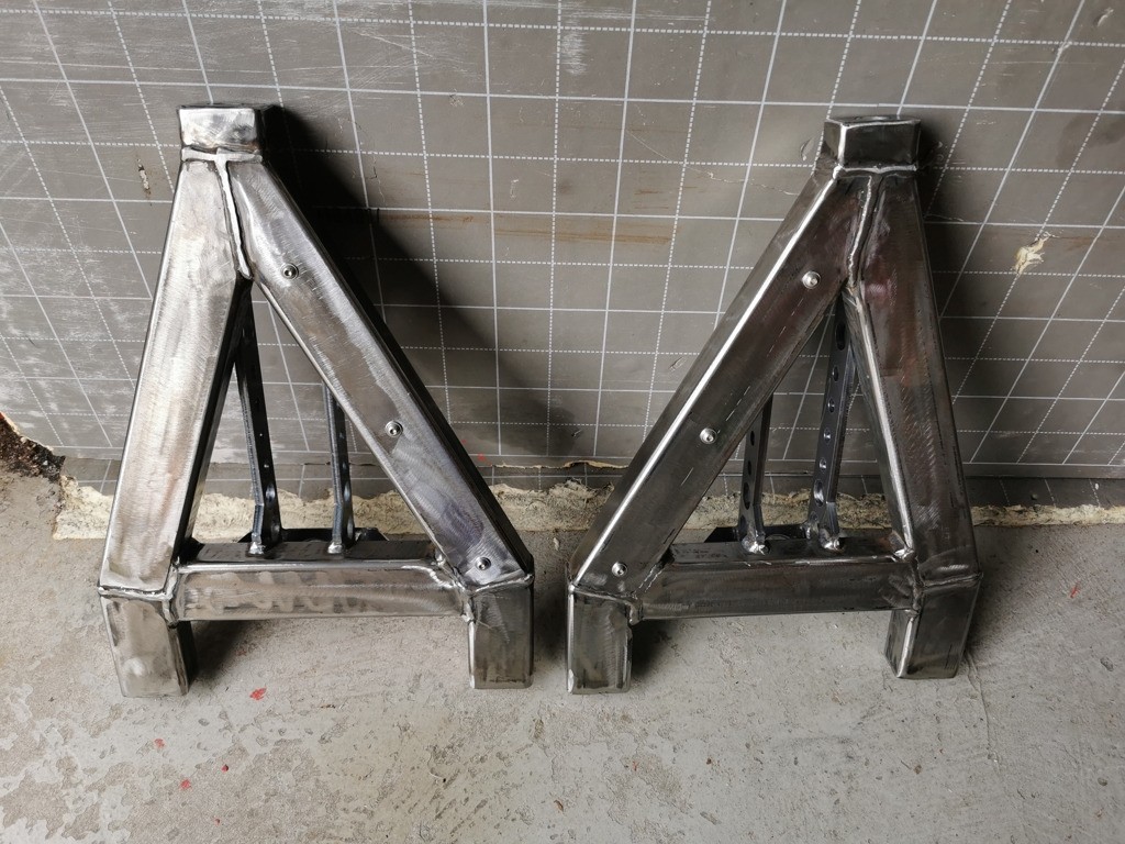
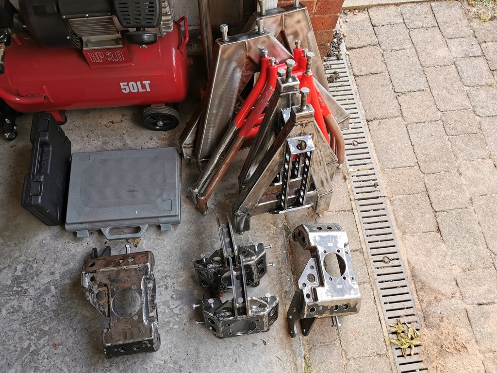
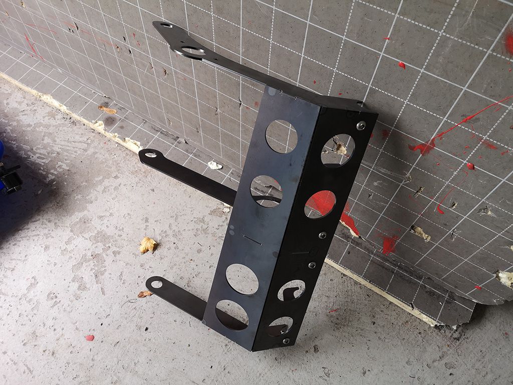
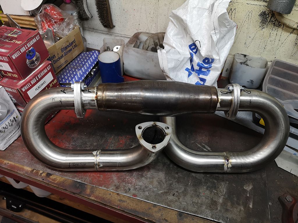
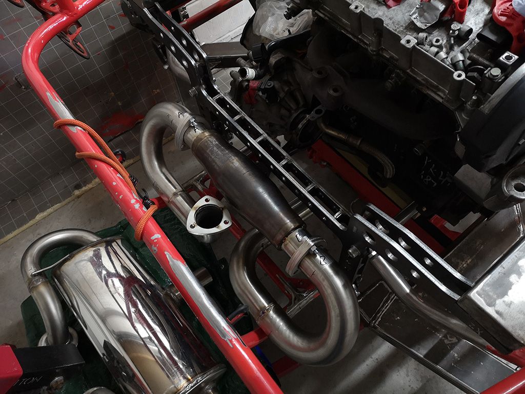
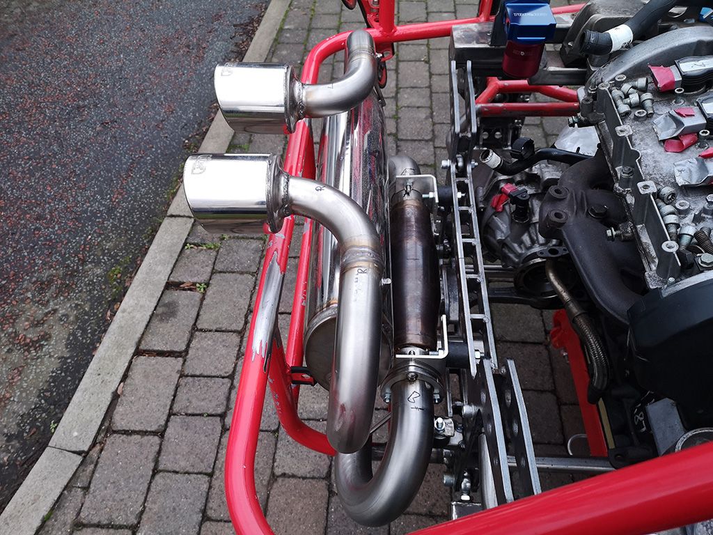
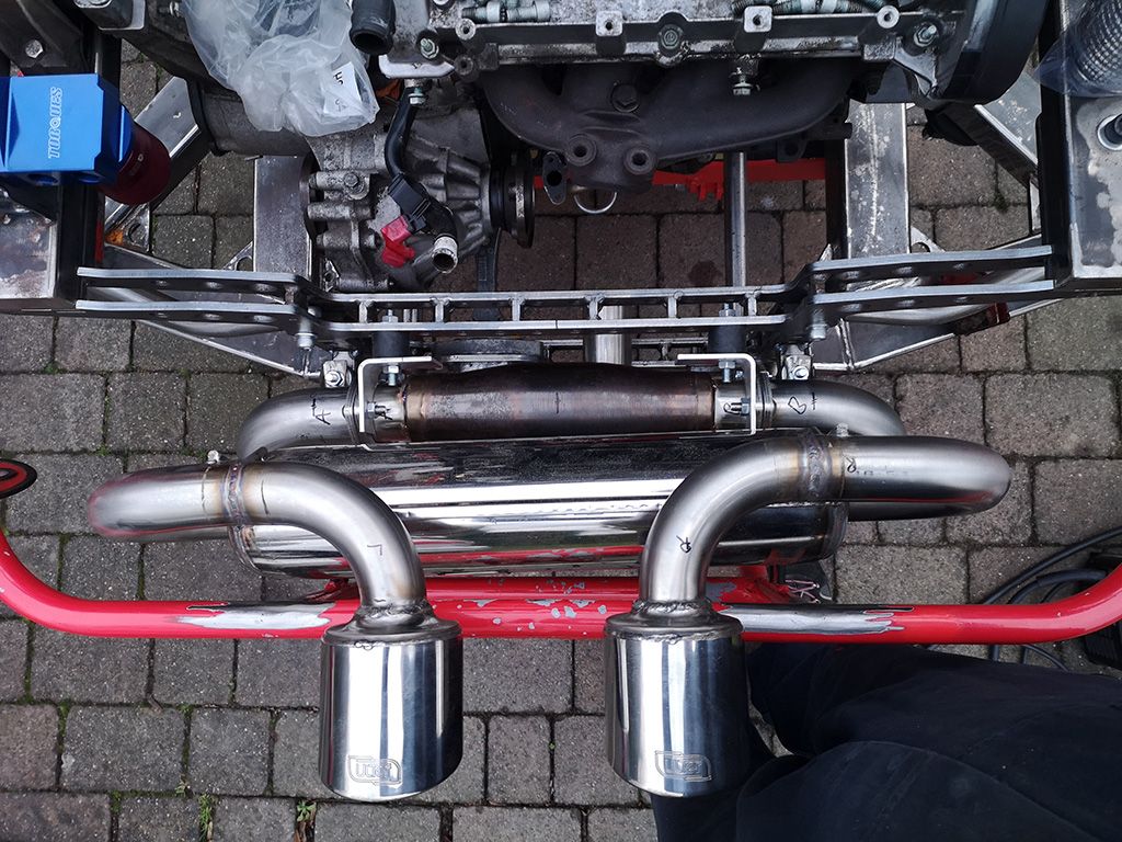
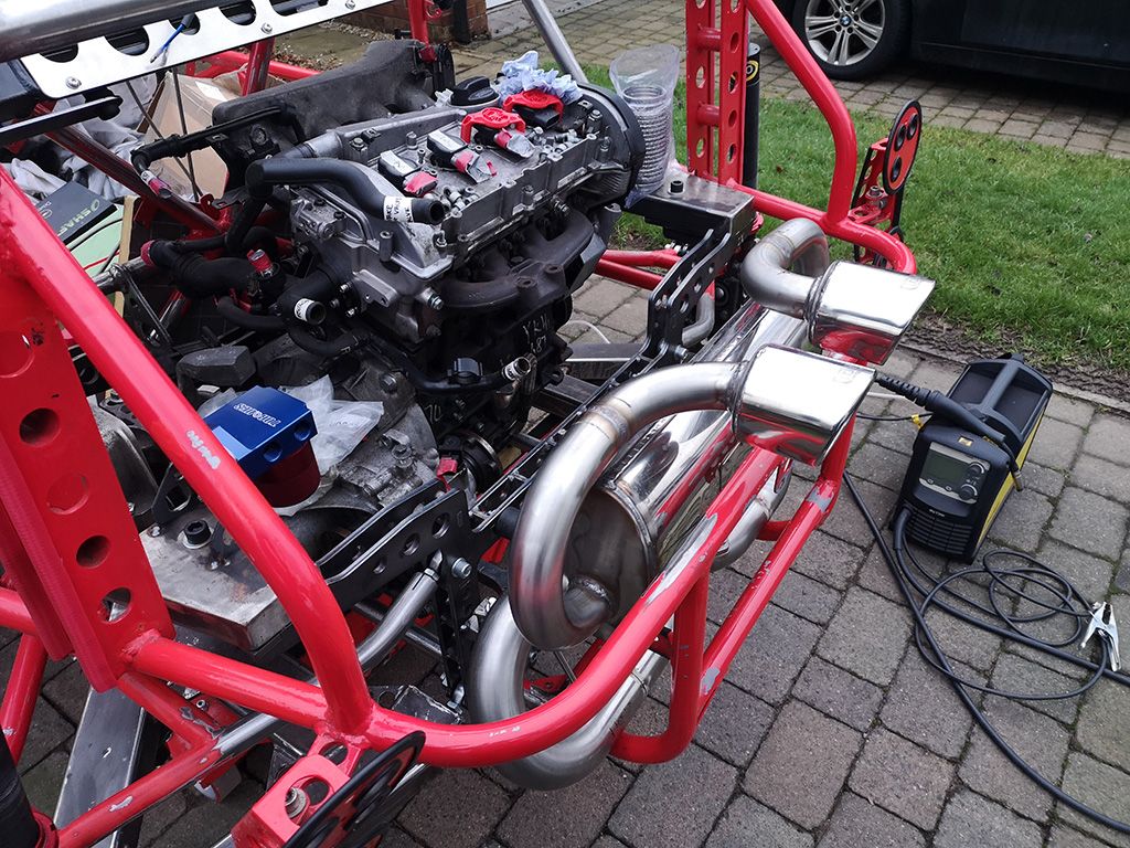
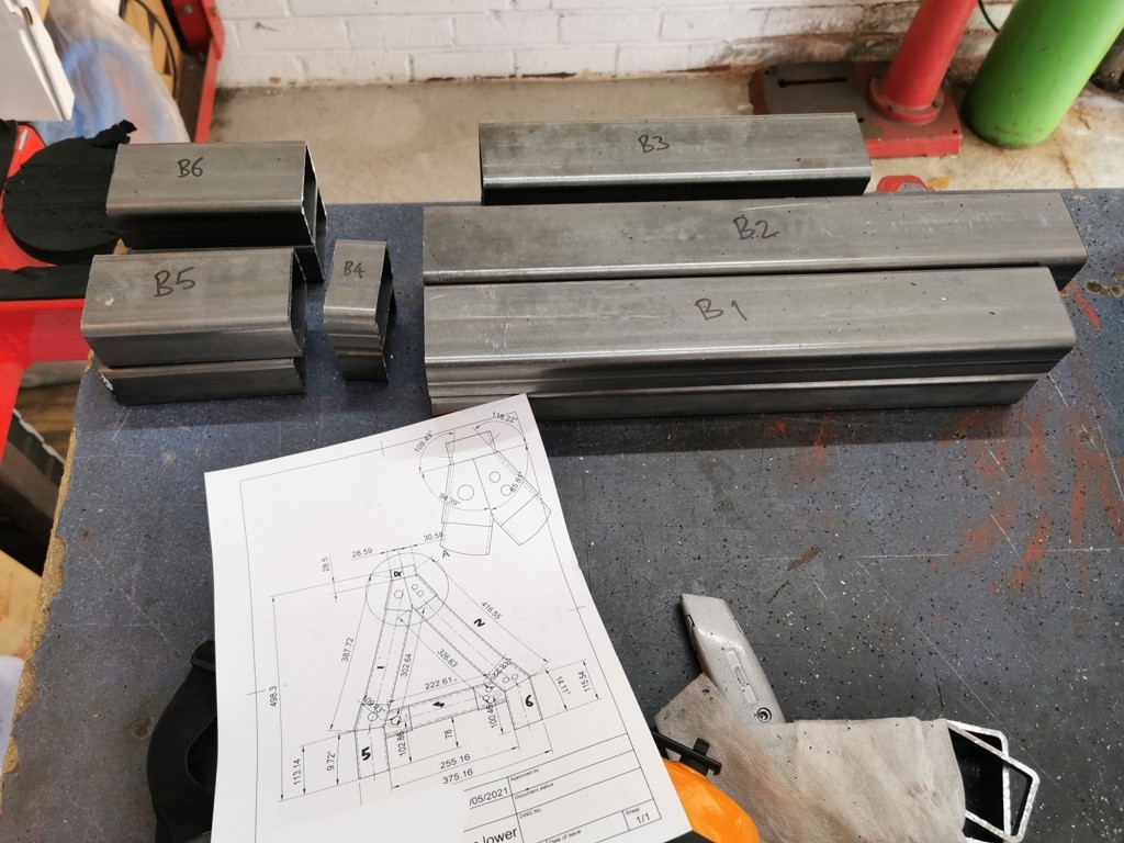
Hi Guys, a bit of an update for you, finally got the next batch of laser cutting done, 8mm 304 stainless parts for the exhaust (manifold flange, and 6 3 bolt flanges to put the system together), 3mm steel for the rad /intercooler mount and the oil cooler mount, 8mm steel for the front hubs, and 3mm aluminium for the rad fan mounts! here are a few pics of the all the lovely bits ;D
304 stainless 8mm thick;

3mm thick steel;
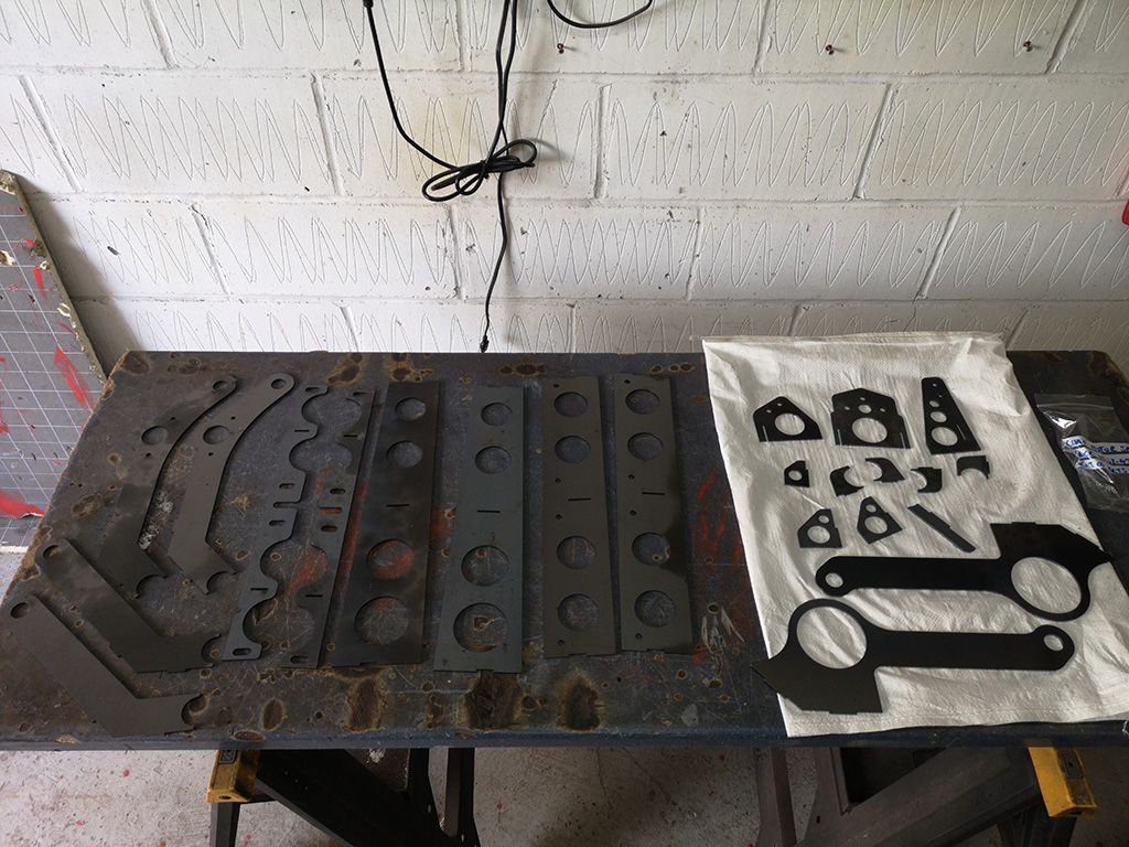
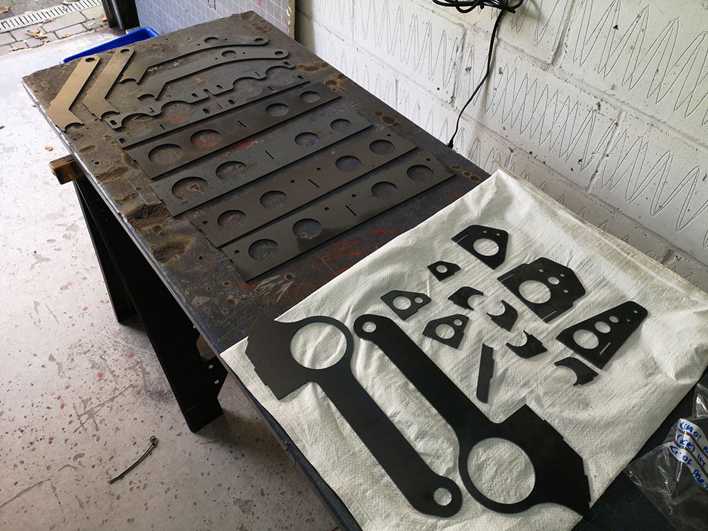
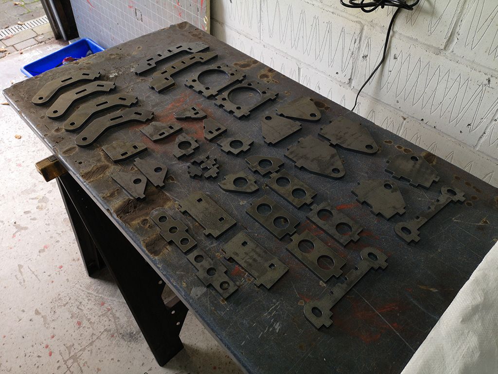
8mm thick steel;

3mm thick Aluminium;

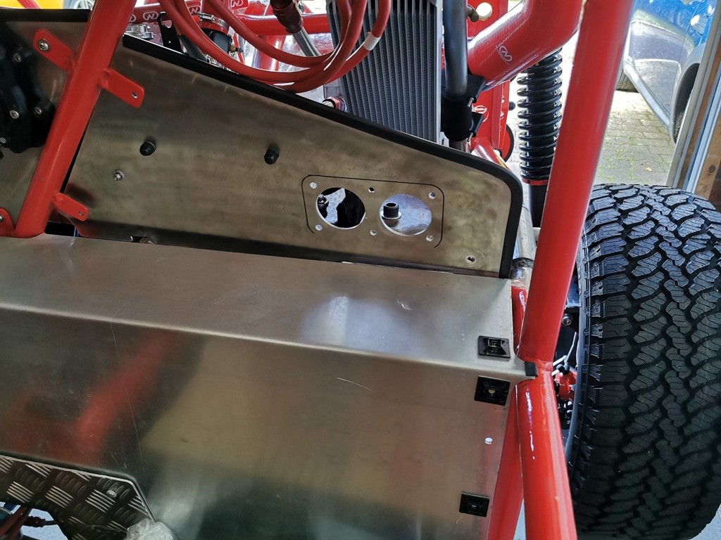
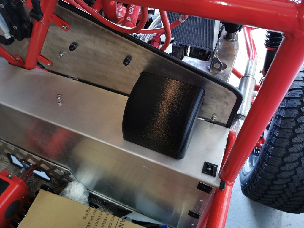
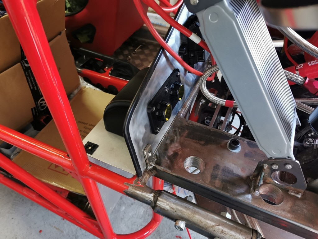
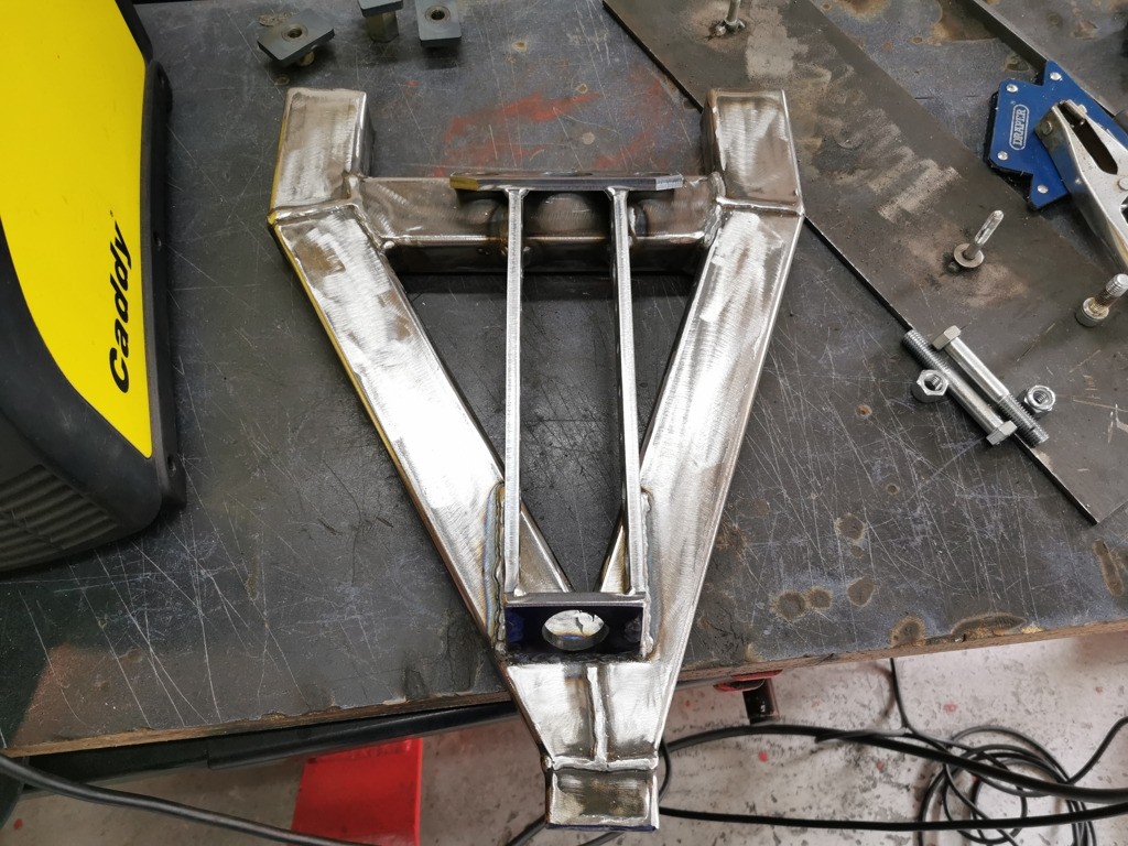
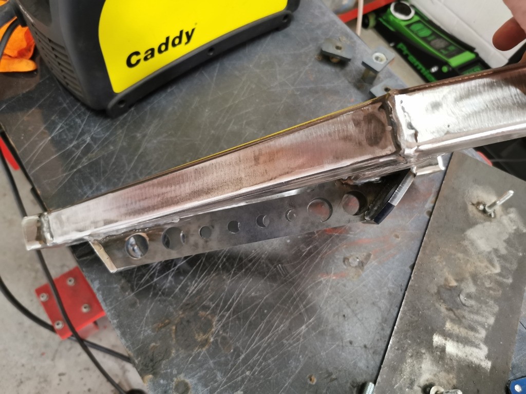
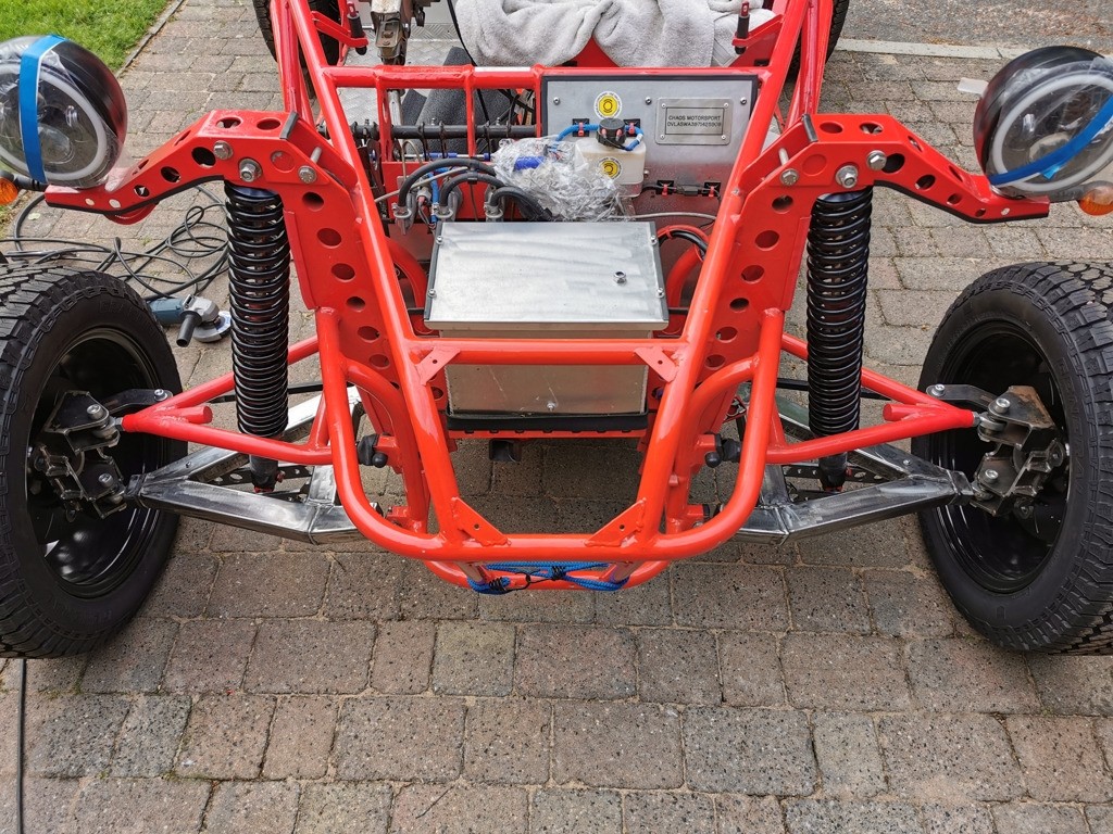
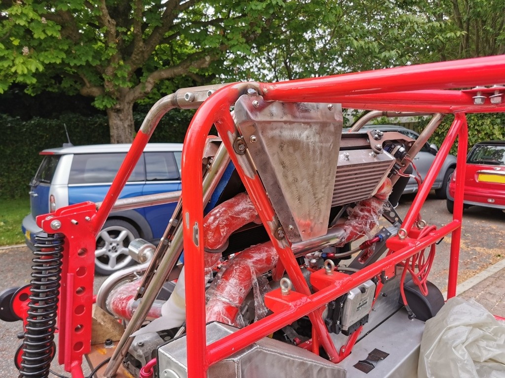
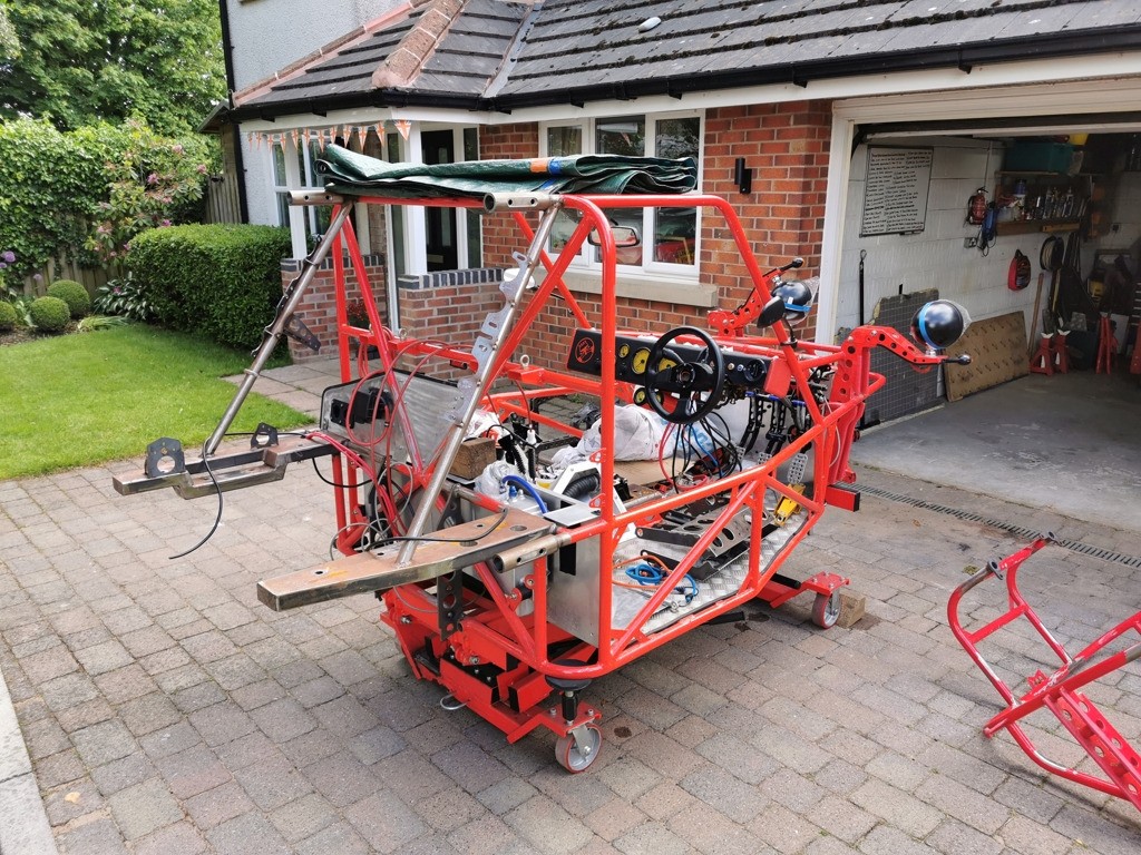
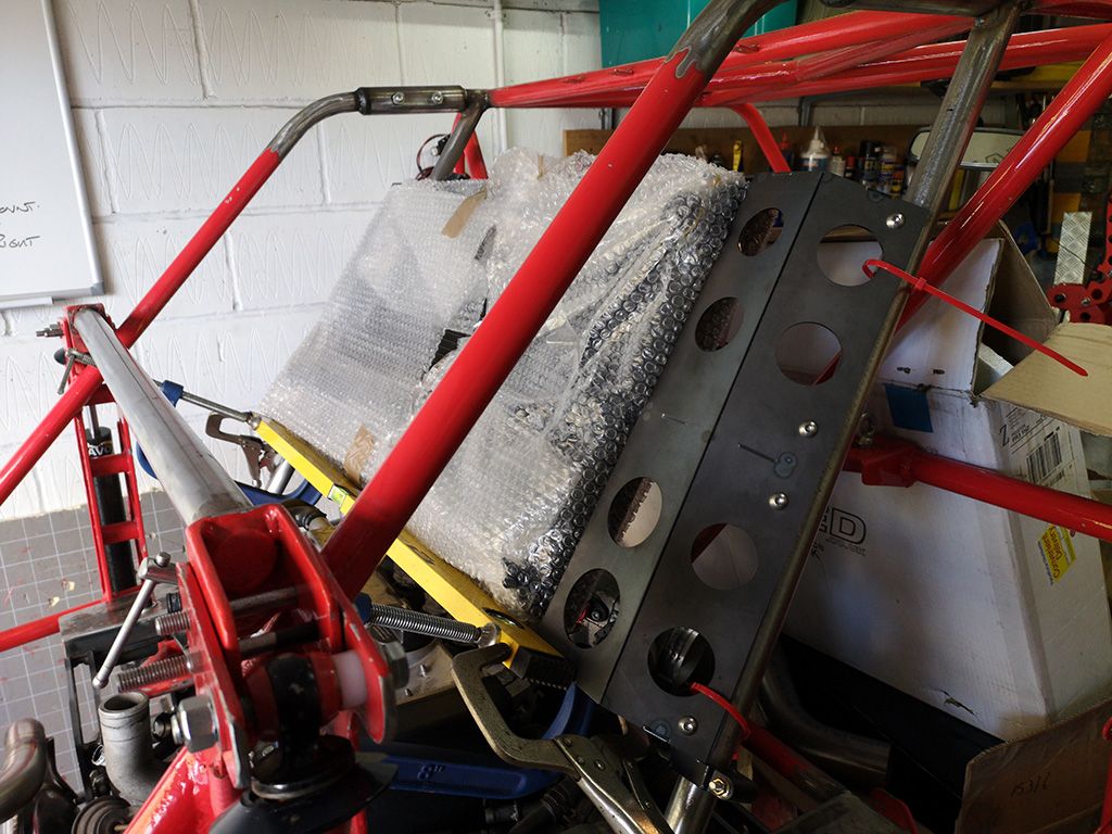
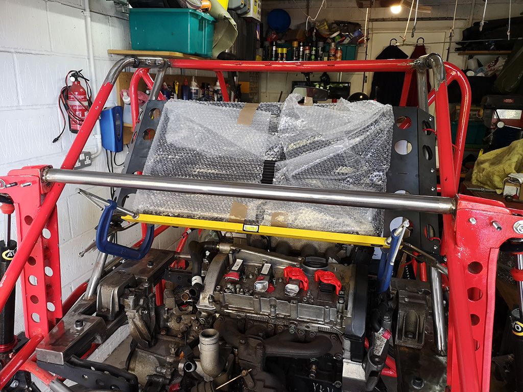
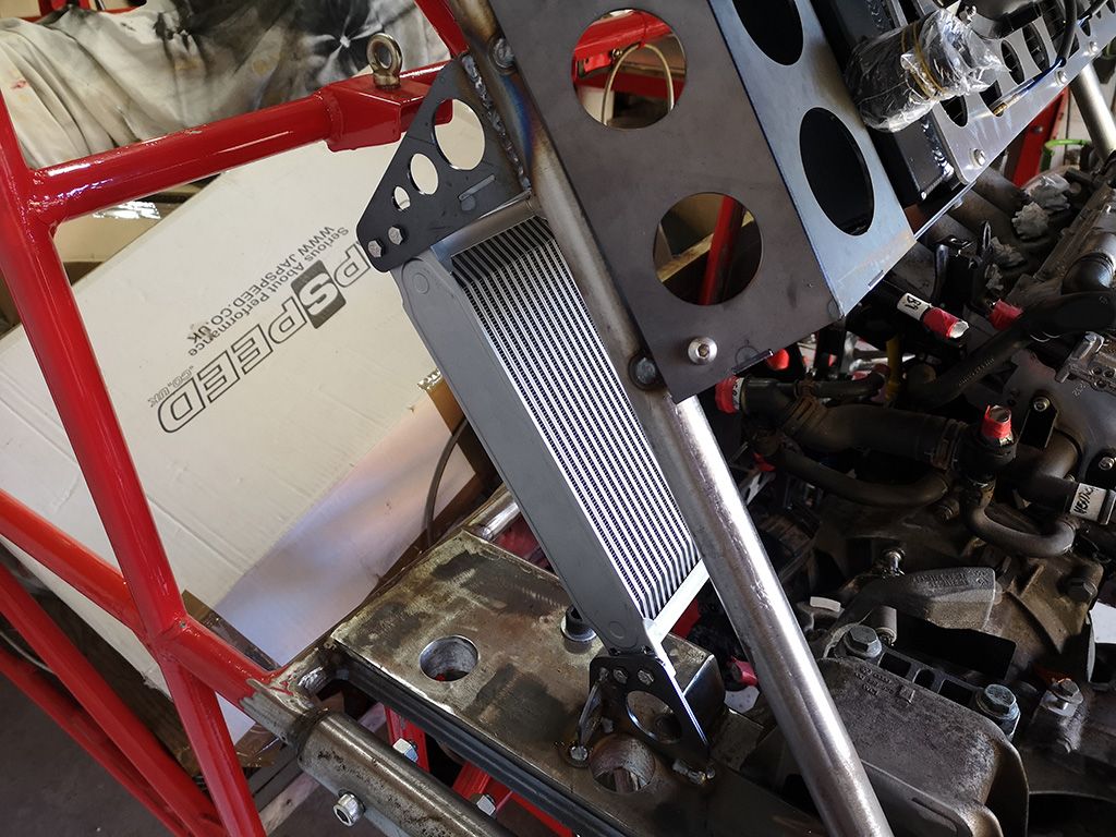
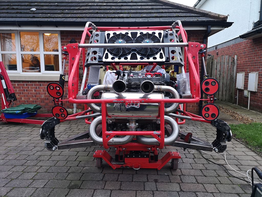
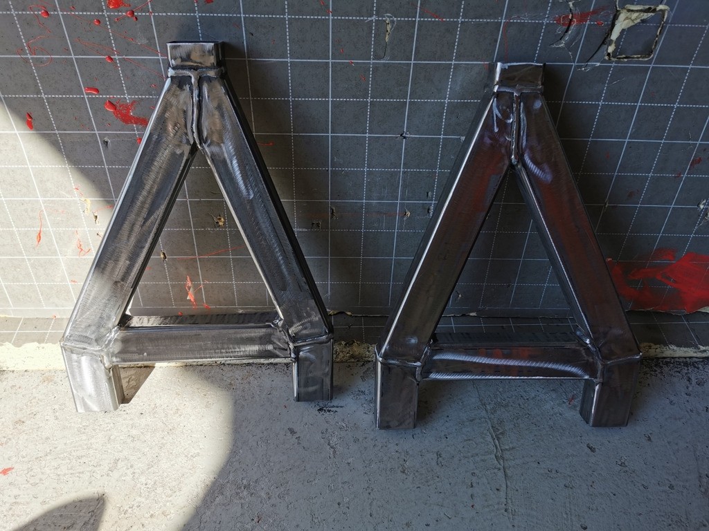
And a few pics of the Rad and Intercooler mount going together and clamped in place on the buggy;
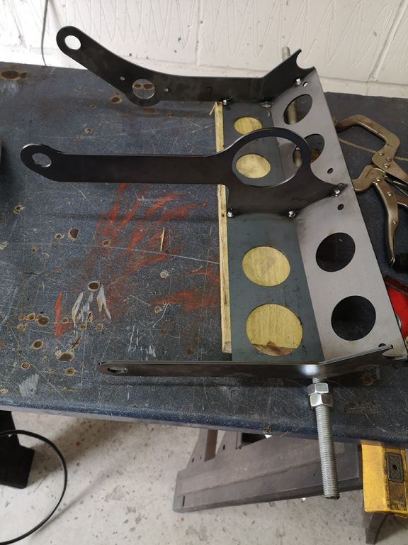

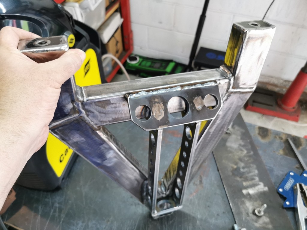
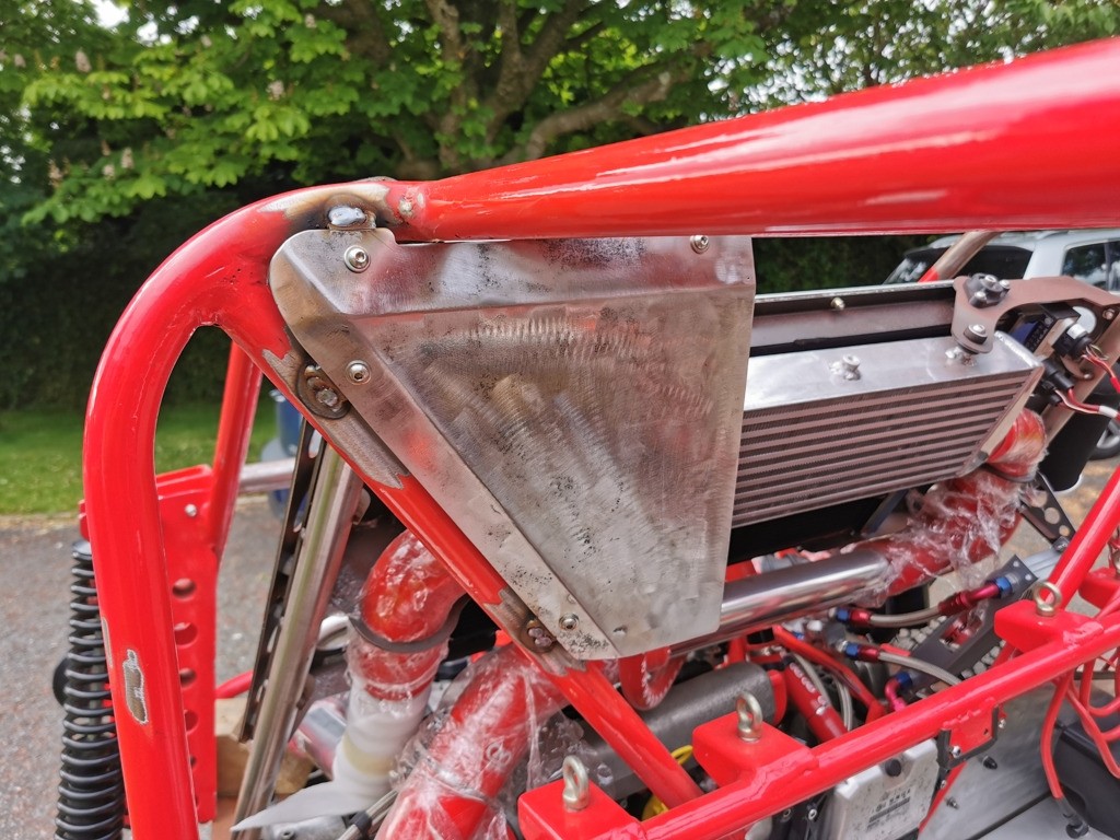
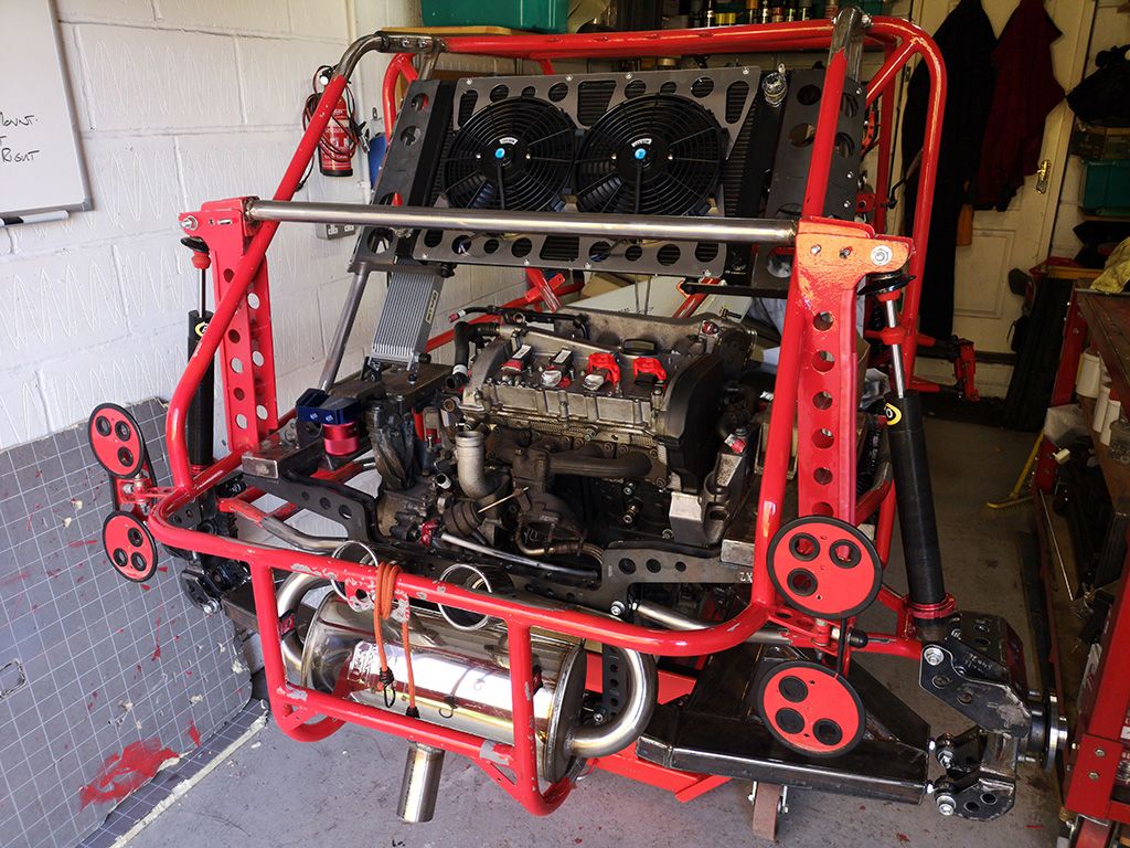
and then roughly mounted - still needs a little work but getting there ;D

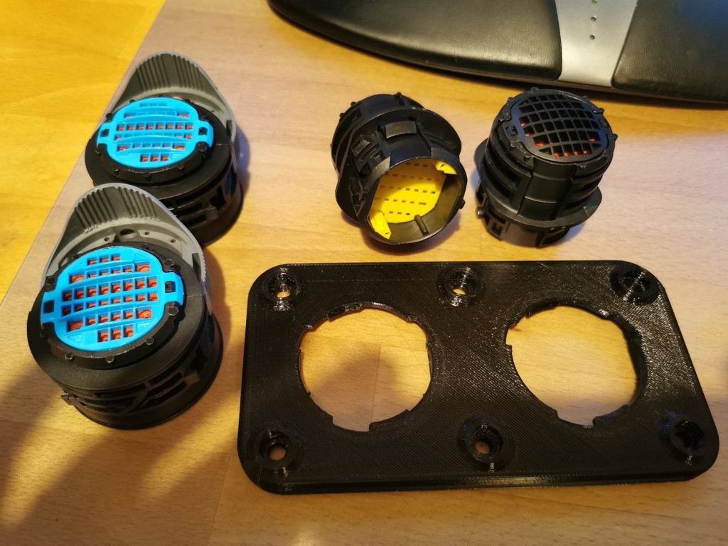
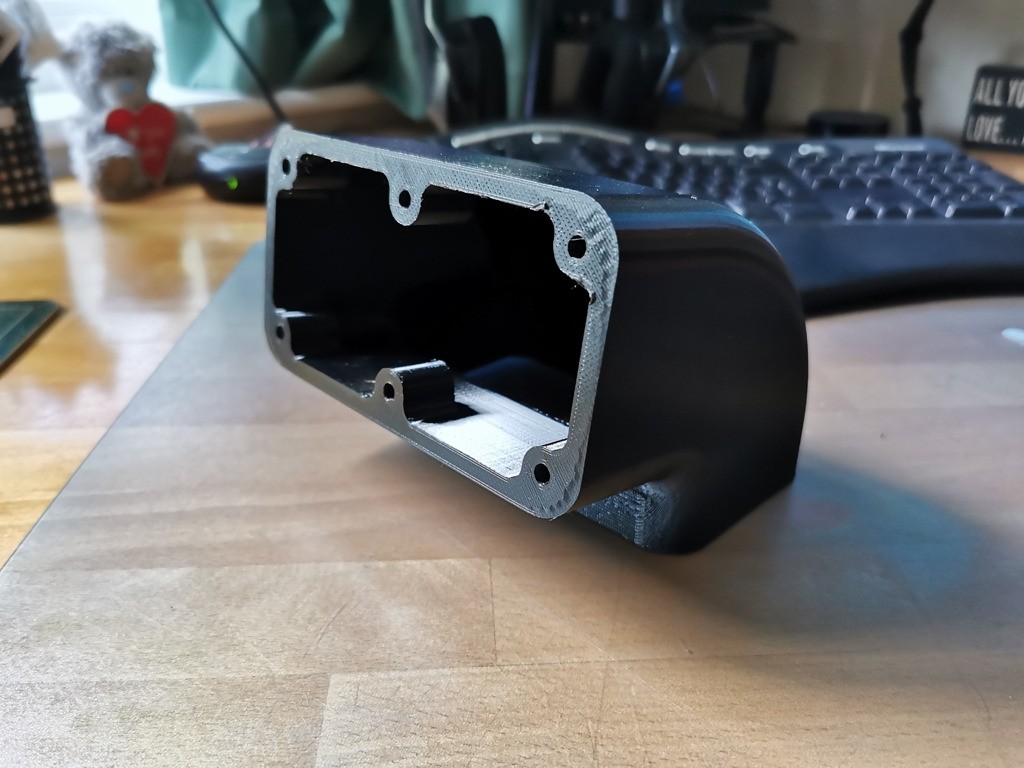
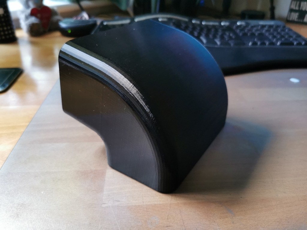
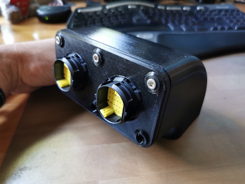
All the rubber bushes have been 3d printed and work really well and the top rad mounts use a 3d printed insert too!! ive been very busy!
so need to finish off and seam weld the rad mount then build up the oil cooler mount for the other side and fit that then I can crack on with the front hubs!!!!!
Getting there very very slowly ! ;D ;D ;D ;D
304 stainless 8mm thick;
3mm thick steel;
8mm thick steel;
3mm thick Aluminium;
And a few pics of the Rad and Intercooler mount going together and clamped in place on the buggy;
and then roughly mounted - still needs a little work but getting there ;D
All the rubber bushes have been 3d printed and work really well and the top rad mounts use a 3d printed insert too!! ive been very busy!
so need to finish off and seam weld the rad mount then build up the oil cooler mount for the other side and fit that then I can crack on with the front hubs!!!!!
Getting there very very slowly ! ;D ;D ;D ;D


 )
)