ChaosMS
Active member
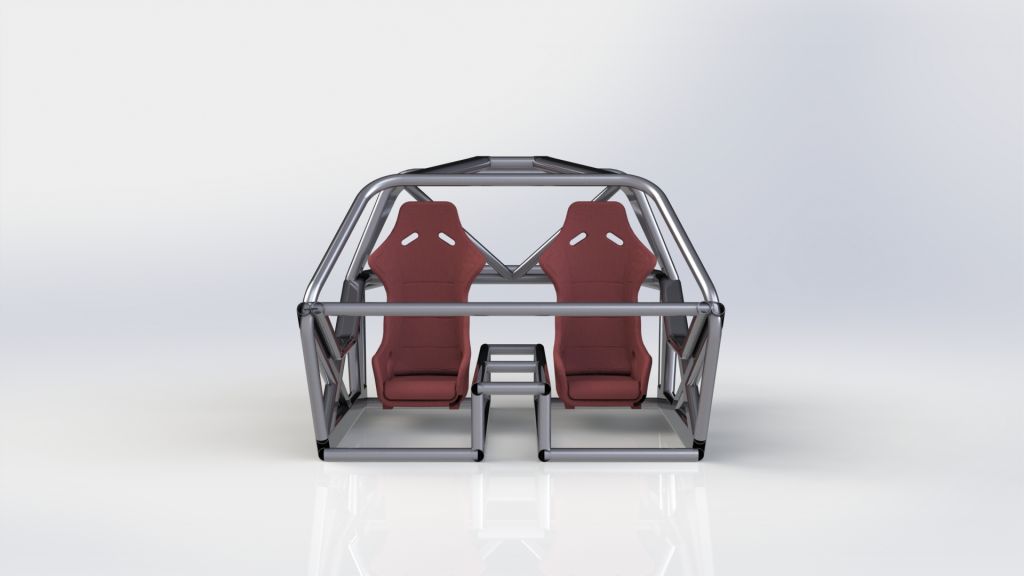
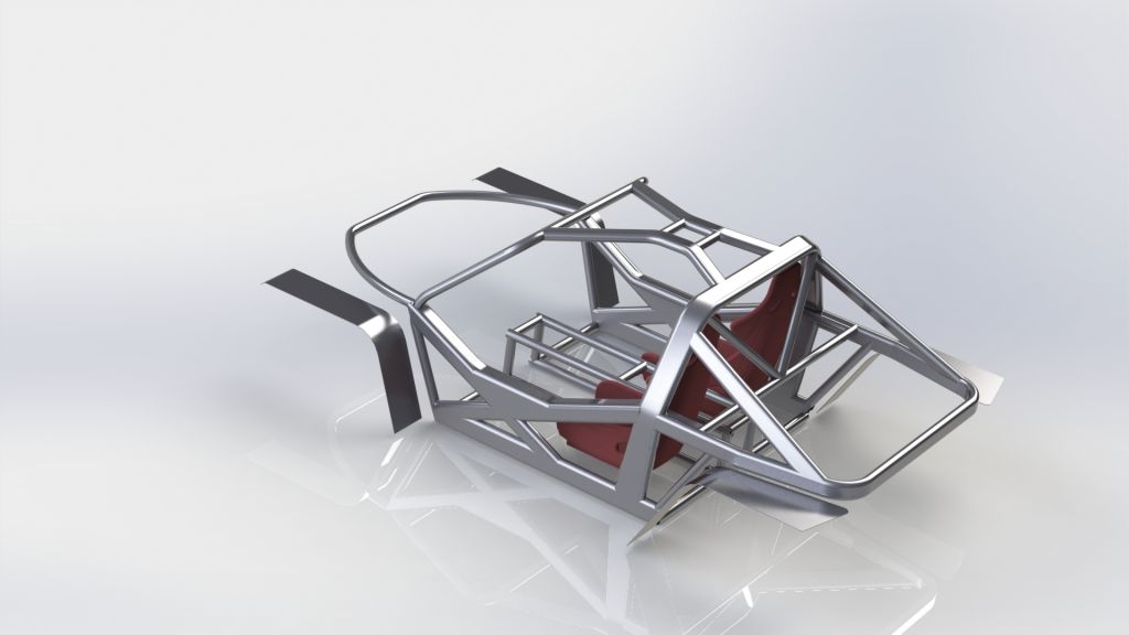
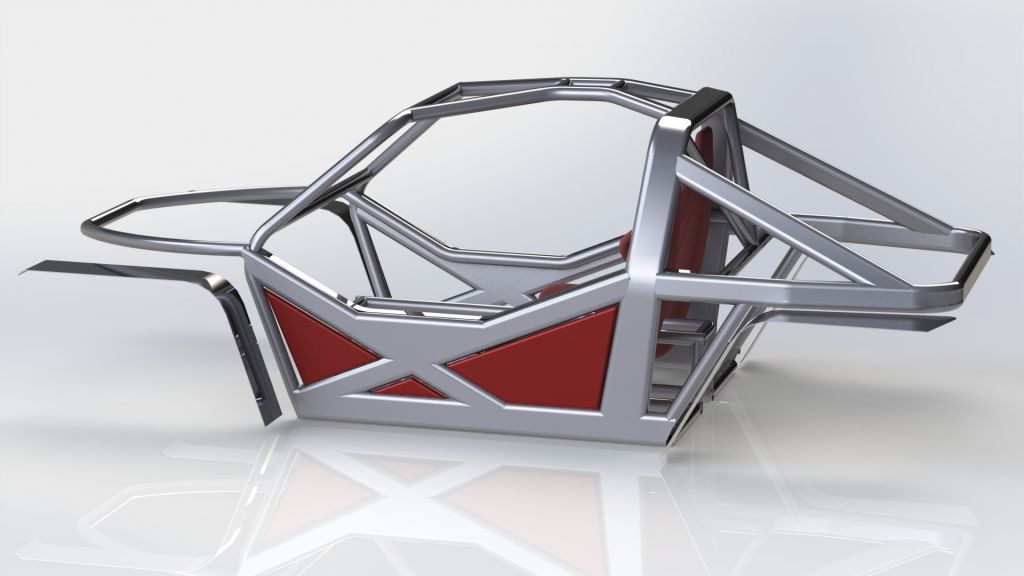
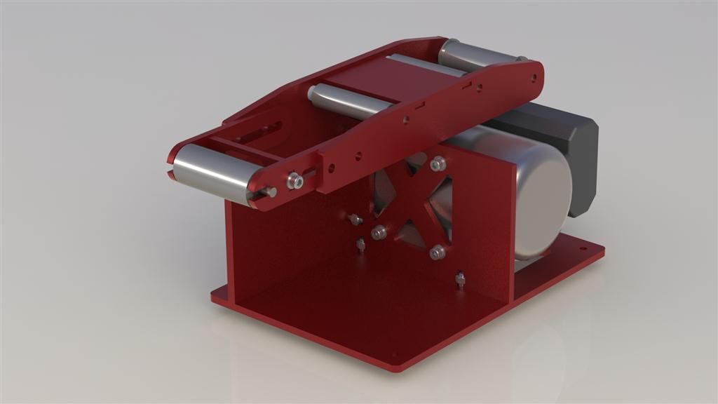
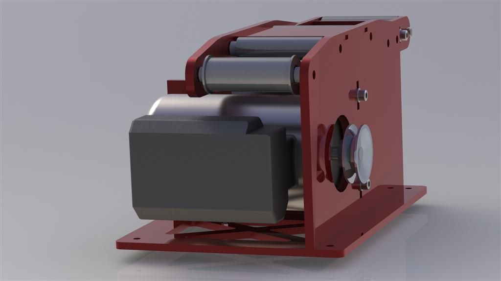
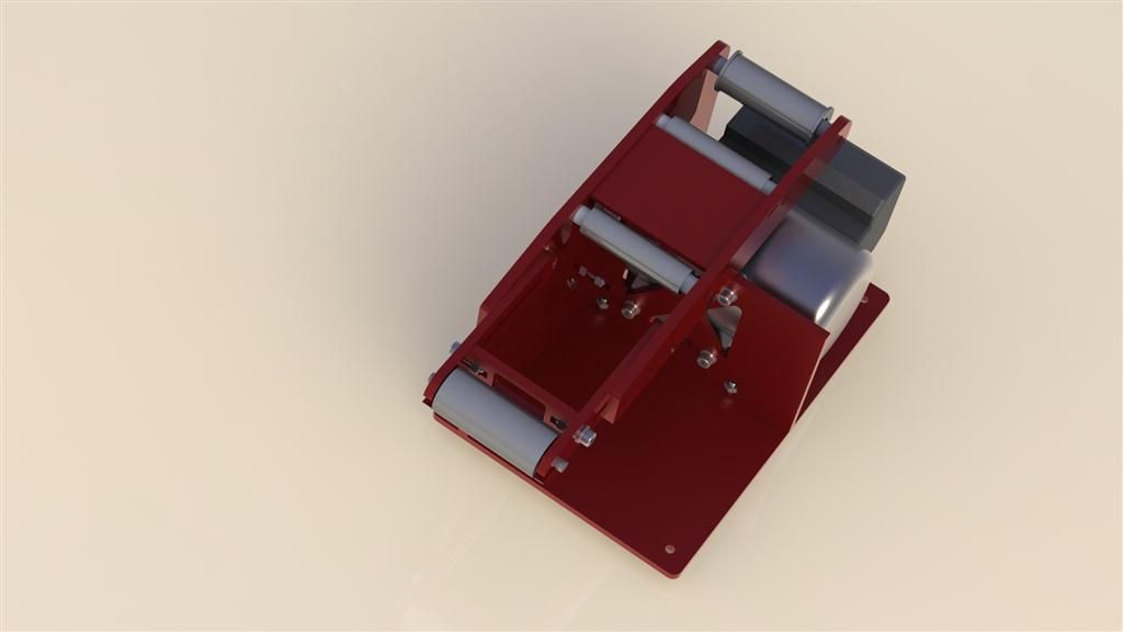
Guys - I've been thinking about the next build!! - It just feels weird that I dont have something to build, dont get me wrong the Chaos Buggy or MKII is running really well but I keep thinking of upgrades that really would work better on a new chassis so Ive started looking for a suitable donor vehicle for the MKIII and started building the chassis in solidworks (well the space model for what needs to go in anyway)
The plan this time is to build a four wheel drive buggy - with a mid engined layout - using a series one AudiTT 180 or 225 Quattro as the donor, looking at the drive train images I can find (and sticking my head under a mates) it would seem possible if a little mental!!
The rear diff (haldex Unit) could be moved to the front and flipped over to make it run the correct way, I would need to rotate the hydraulic clutch system it has to ensure the oil flow is correct but it looks possible from what I can see, all the driveshafts would need to be modified but thats nothing complex, the main technical issue is going to be the prop-shaft drive from the gearbox, and I think I'm going to bring the propshaft under the engine and chain drive it from the existing take off point using 3 or 4 chain width chain similar to those used on a Nissan 4 wheel drive system
And to speed up the construction im going to get the whole lot built in solidworks and send as much as possible to be water cut locally so no more hole saw cutting and masses of grinder and flap wheel work - design all the parts to be cut flat with assembly lugs and then welded together.
Also thinking of building the frame in 3 parts having the centre tub as one and the engine and rear cage and rear suspension as another with front suspension and cage as the final part, problem with this is making it structurally as strong as an un-joined frame I suppose - I need to look at what that could work like and if the stresses on the joints are going to be too high
Anyway these are my initial thoughts - what do you think?
")