Ultralite Buggy Build

ChaosMS

Active member
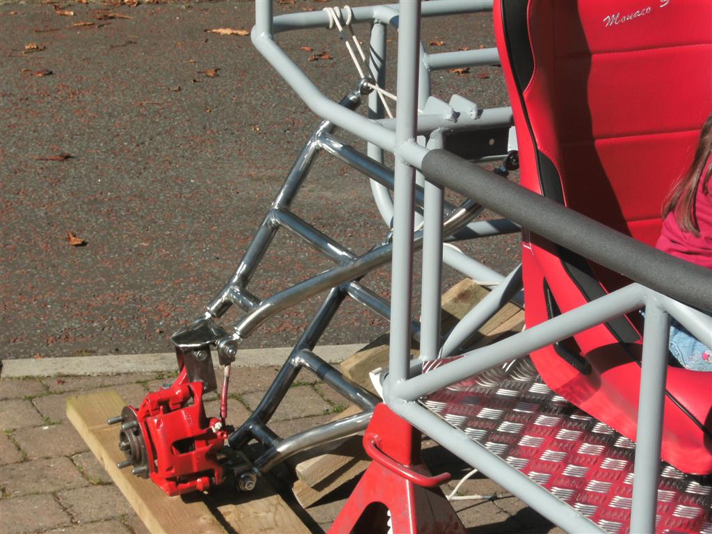
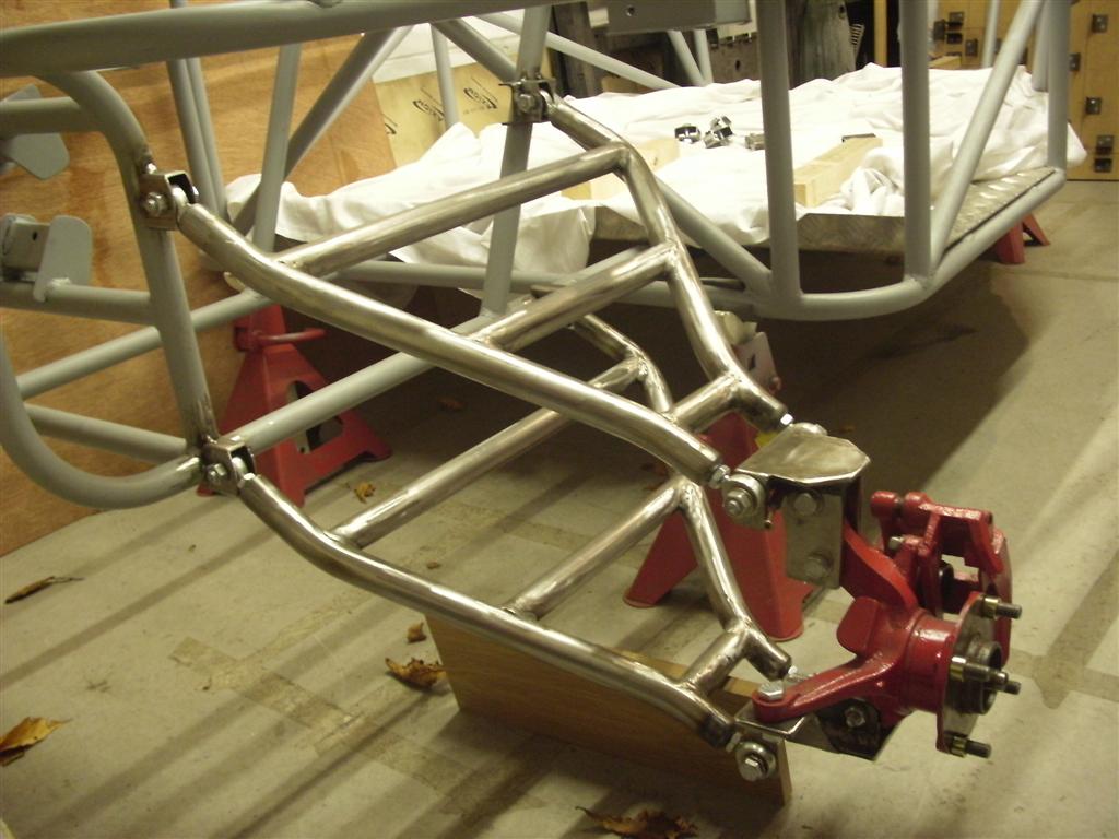
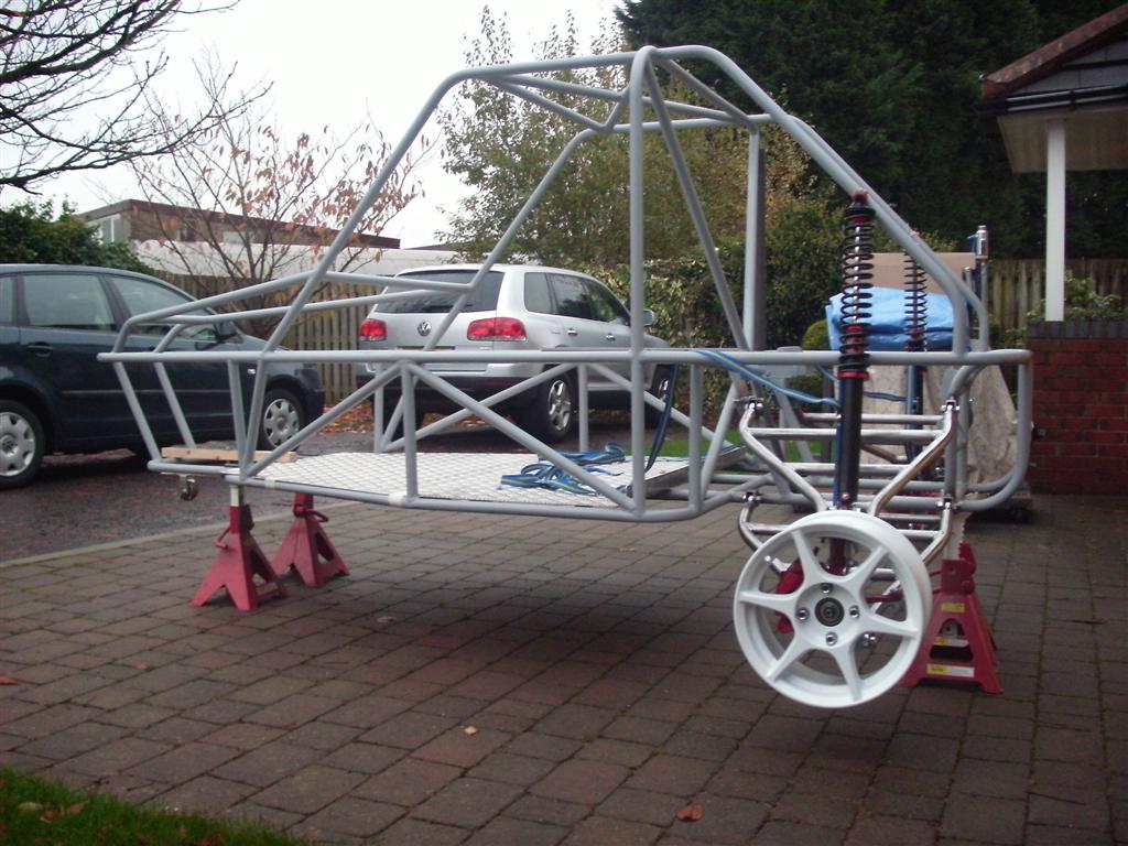
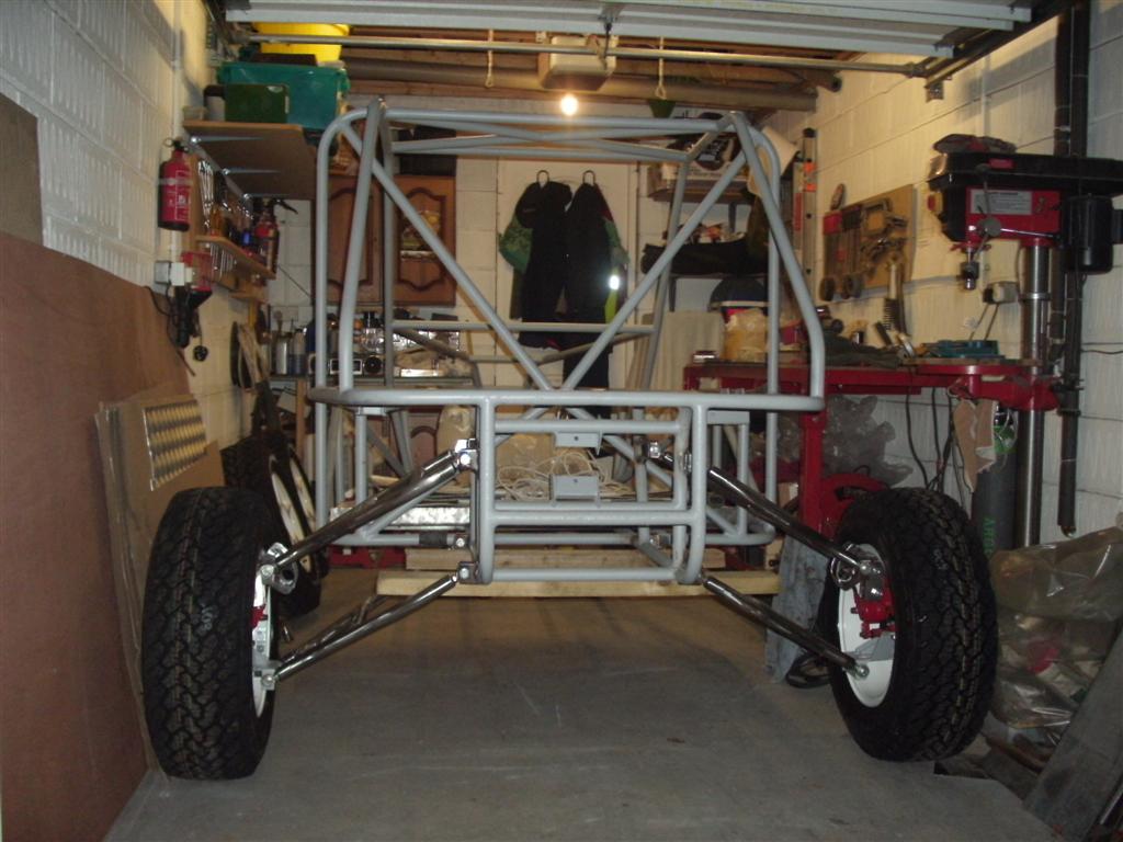
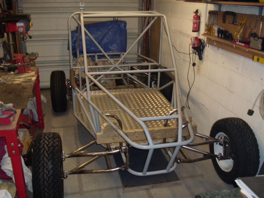
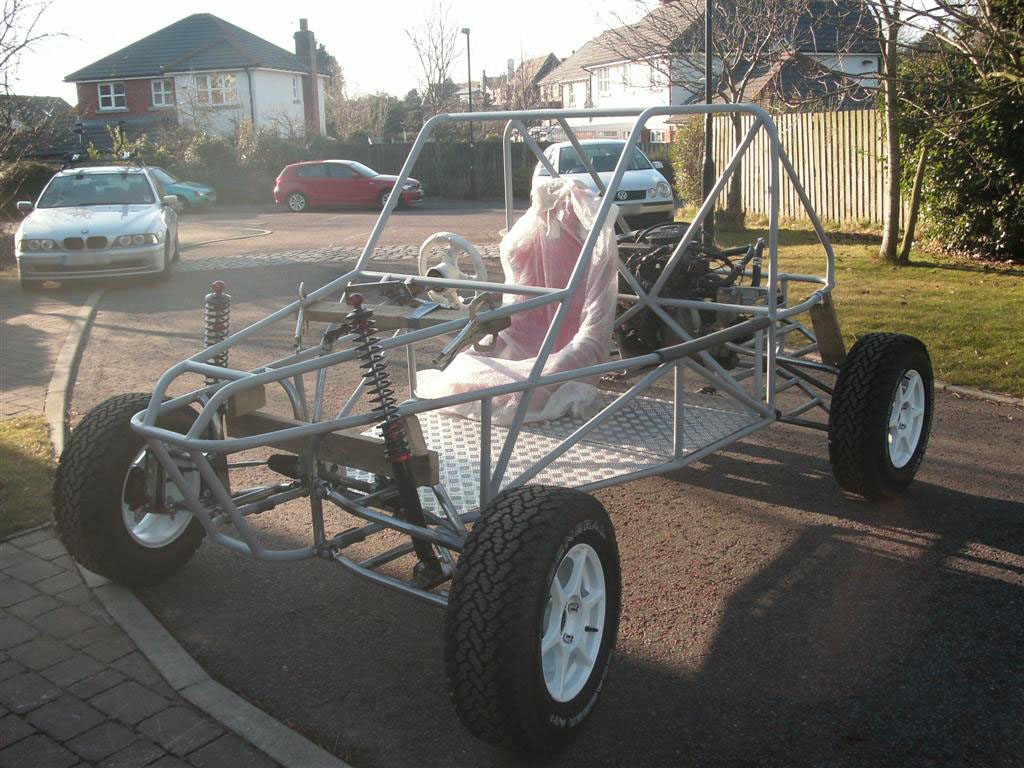
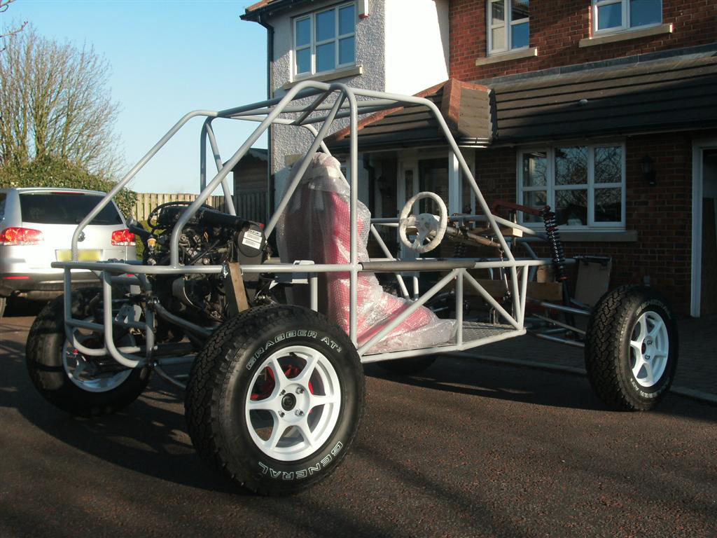
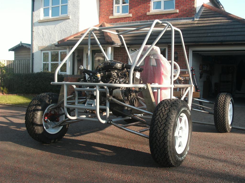
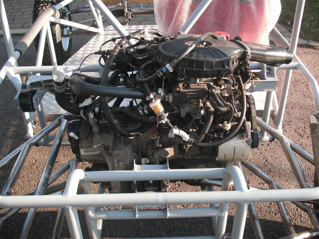
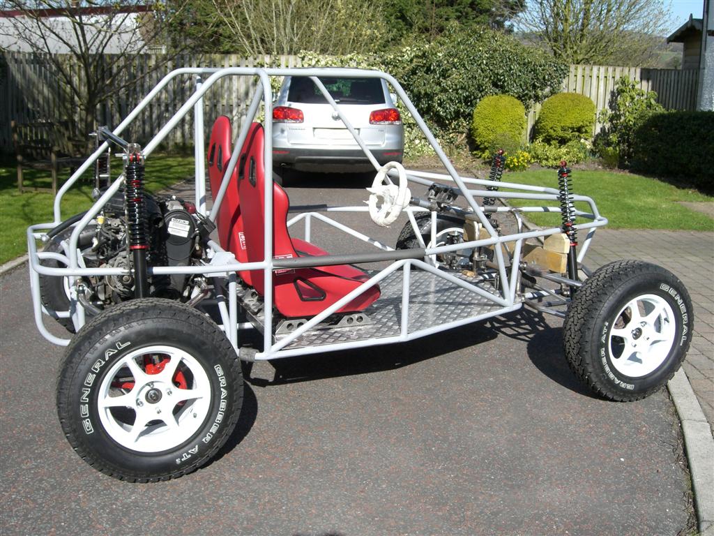
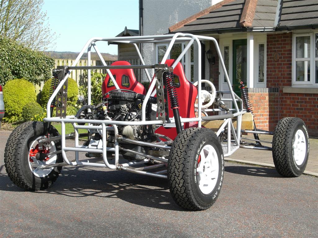
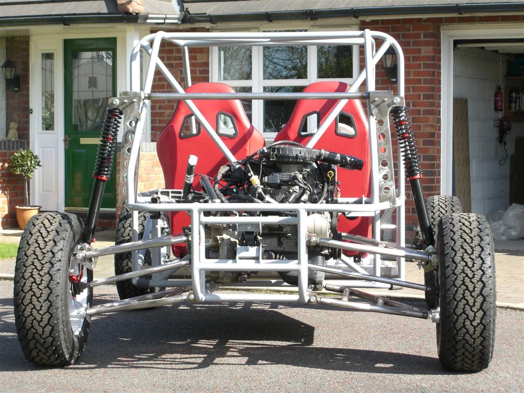
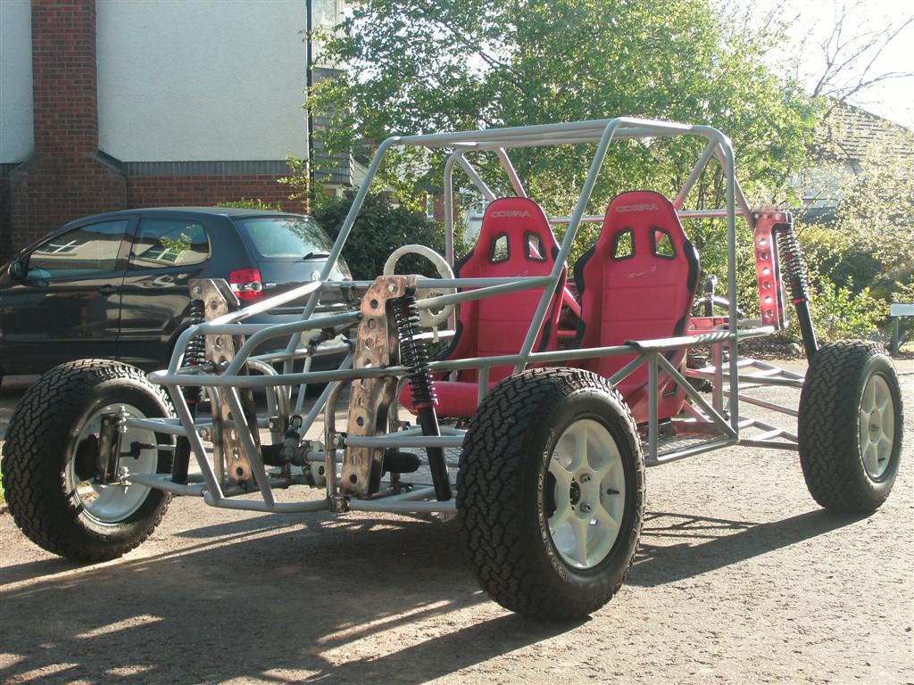
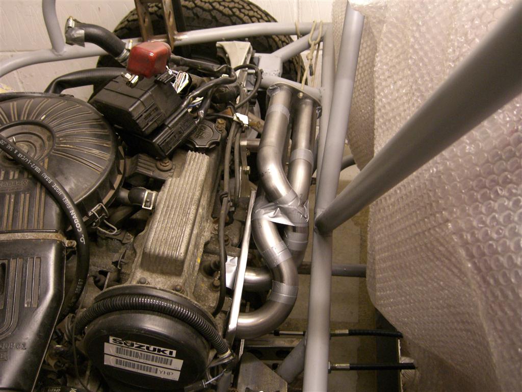
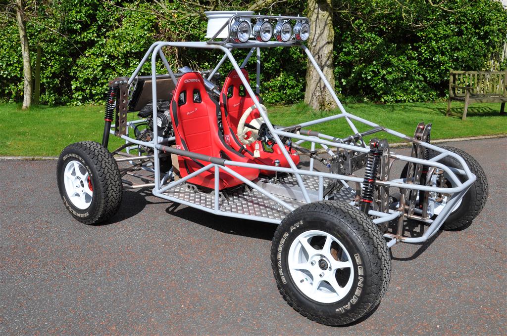
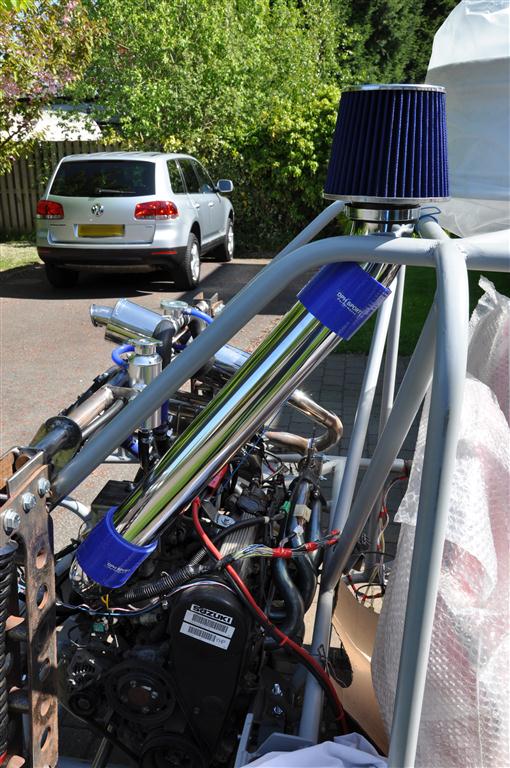
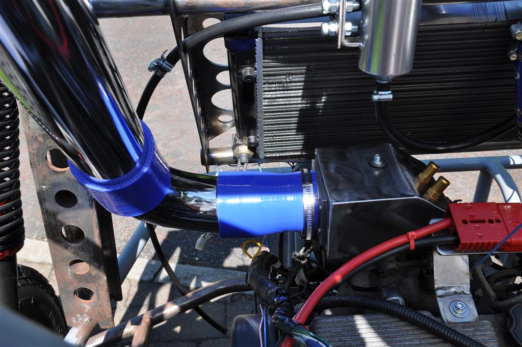
Hi everyone, New to forum so just thought I would post a few pics of my buggy project here in the UK, still got a bit to do but the project is going well so far, without too many major issues (those will come when I try to get it registered for road use). The buggy has been designed by myself (and a good bit of CAD software) and is powered by a suzuki swift engine and box.

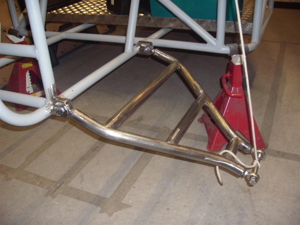
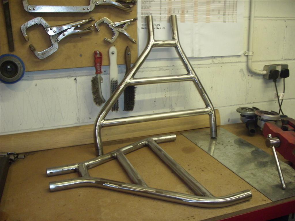
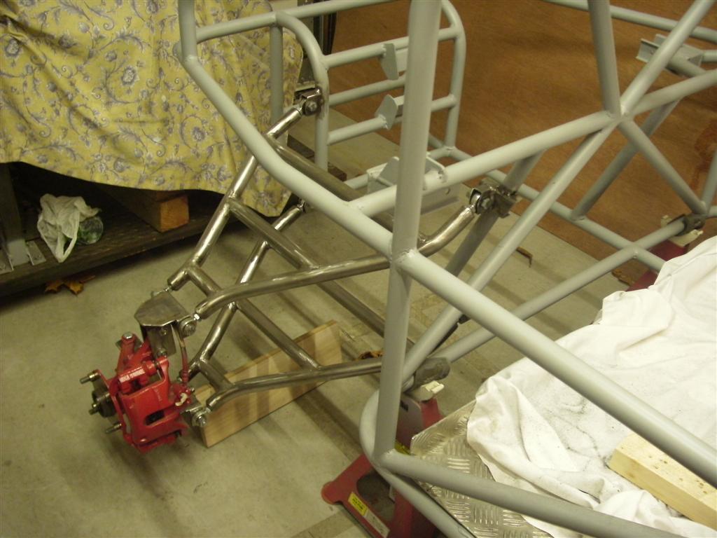
Anyway I have a LOT of build pics over on my build site but here are a few to get you started :-

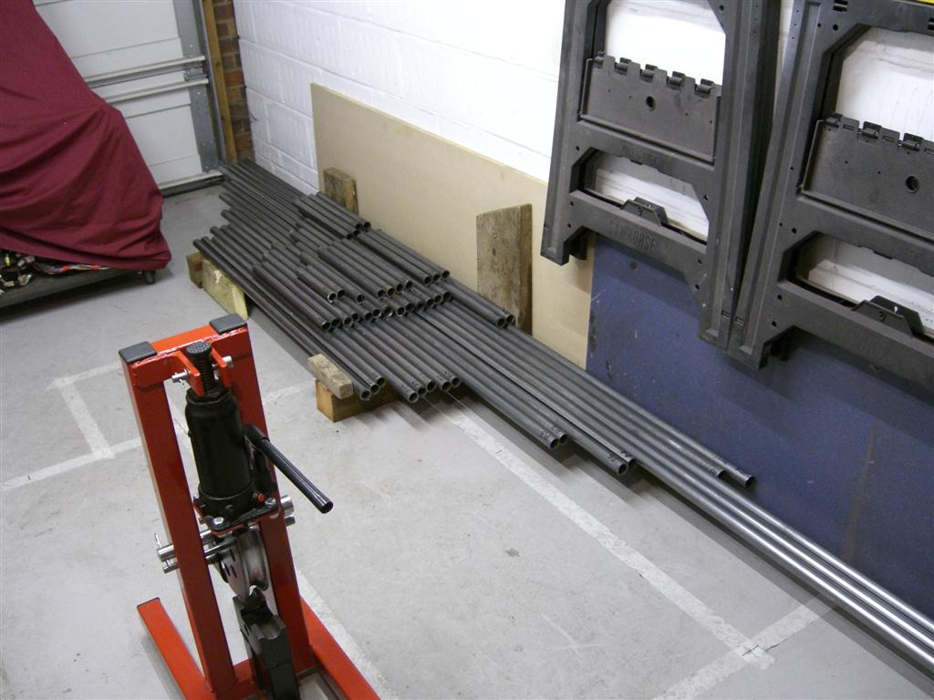
Day 1 280 feet of 1.25" (32mm if your in the UK) 2mm wall ERW tube - it dosent look much once its chopped up!
build_diary3_web.jpg


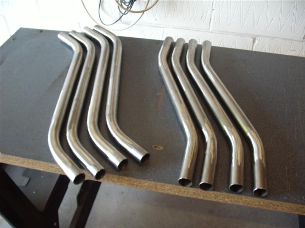
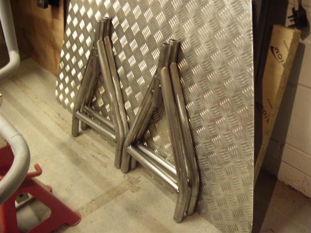
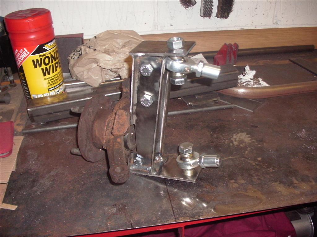
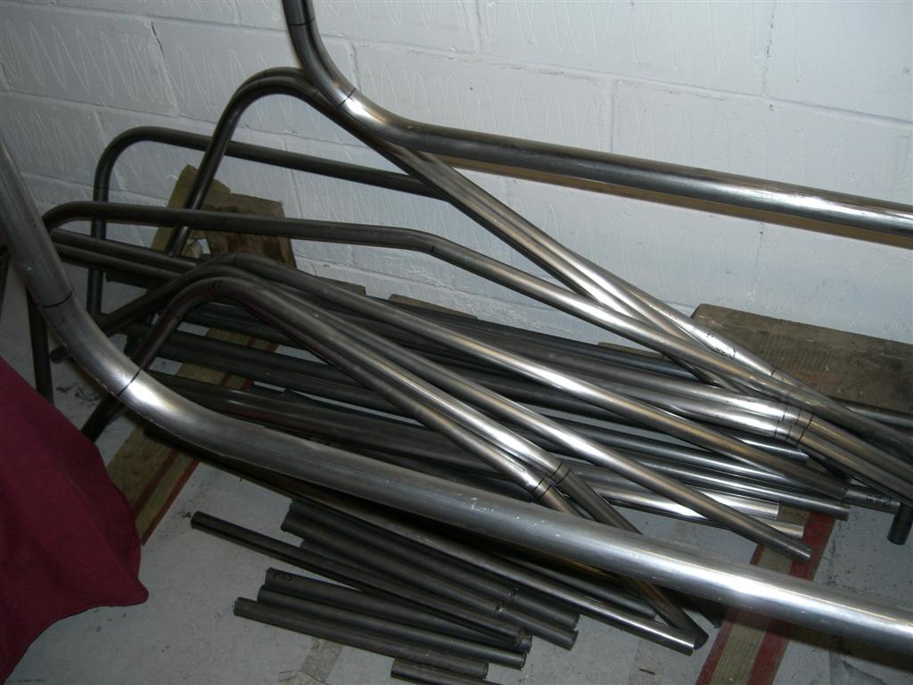
Majority of chassis parts bent to correct angle with the homemade tube bender:-
build_diary18_web.jpg


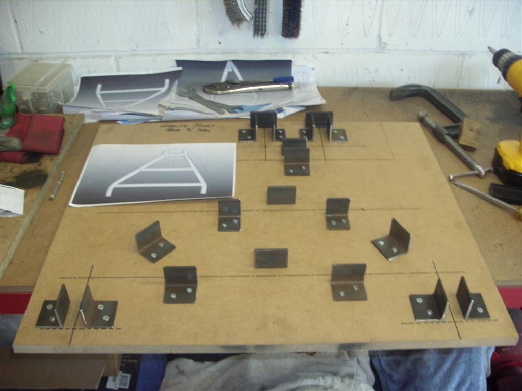
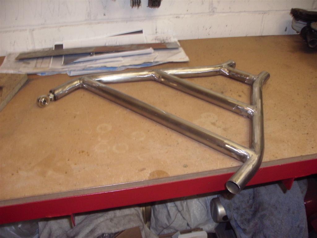
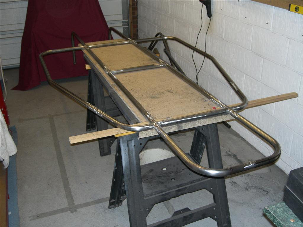
Start of the lower chassis section:-
build_diary24_web.jpg


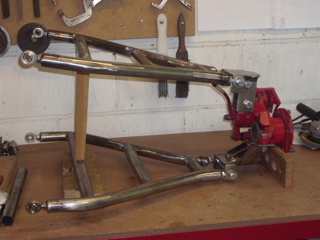
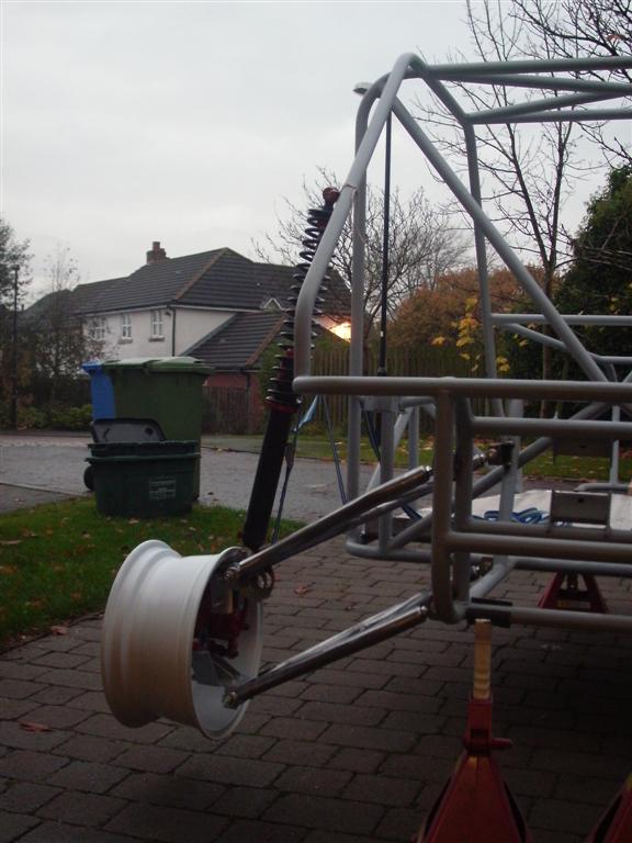
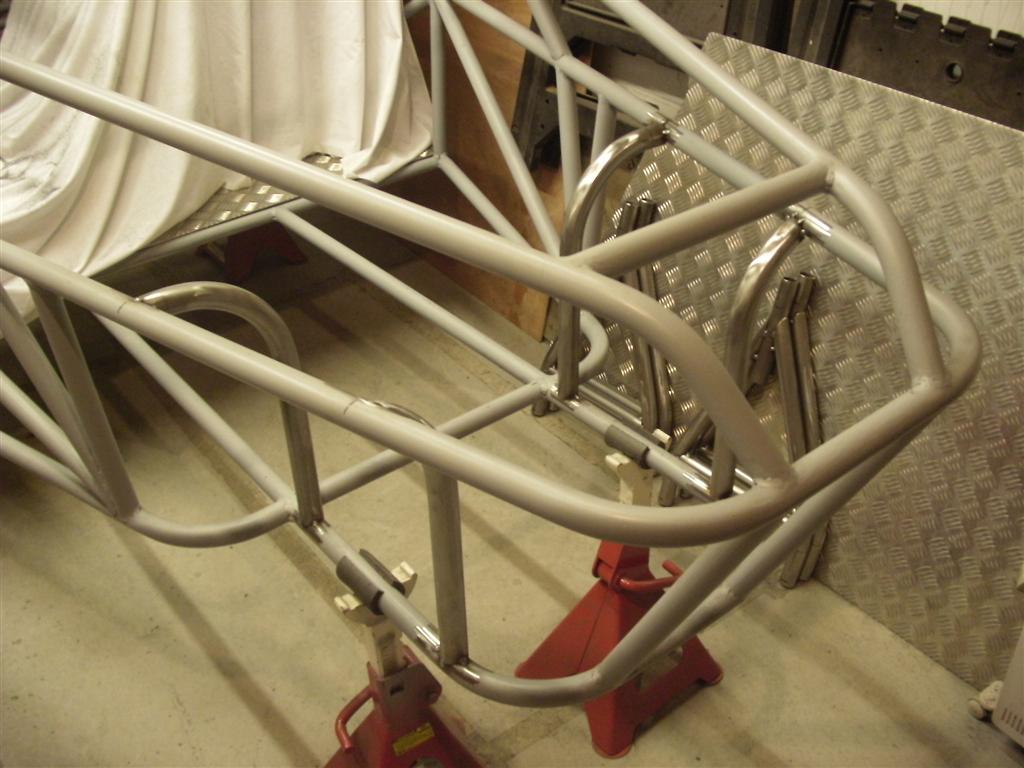
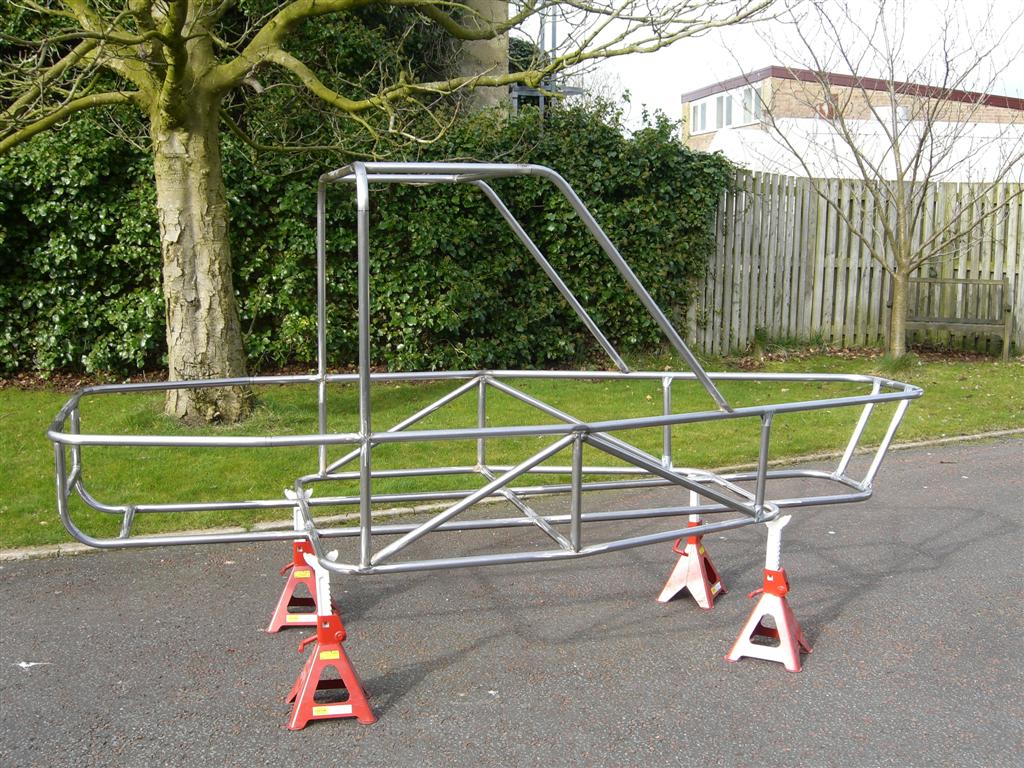
Chassis main roll over bar and rear cage:-
build_diary39_web.jpg


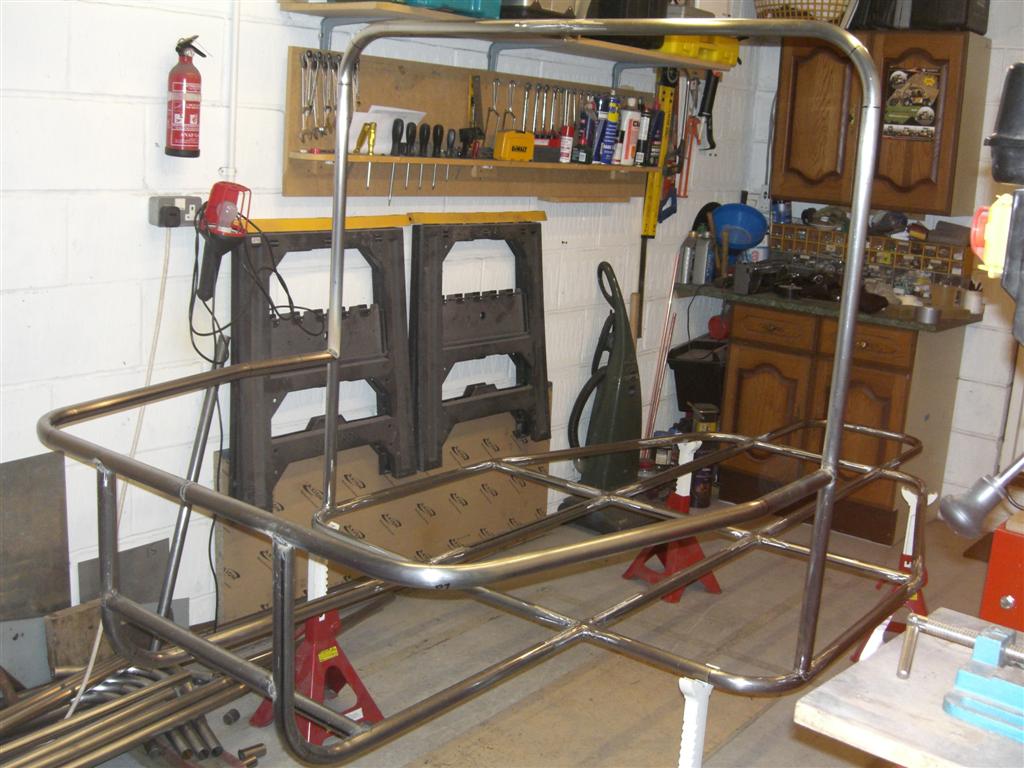
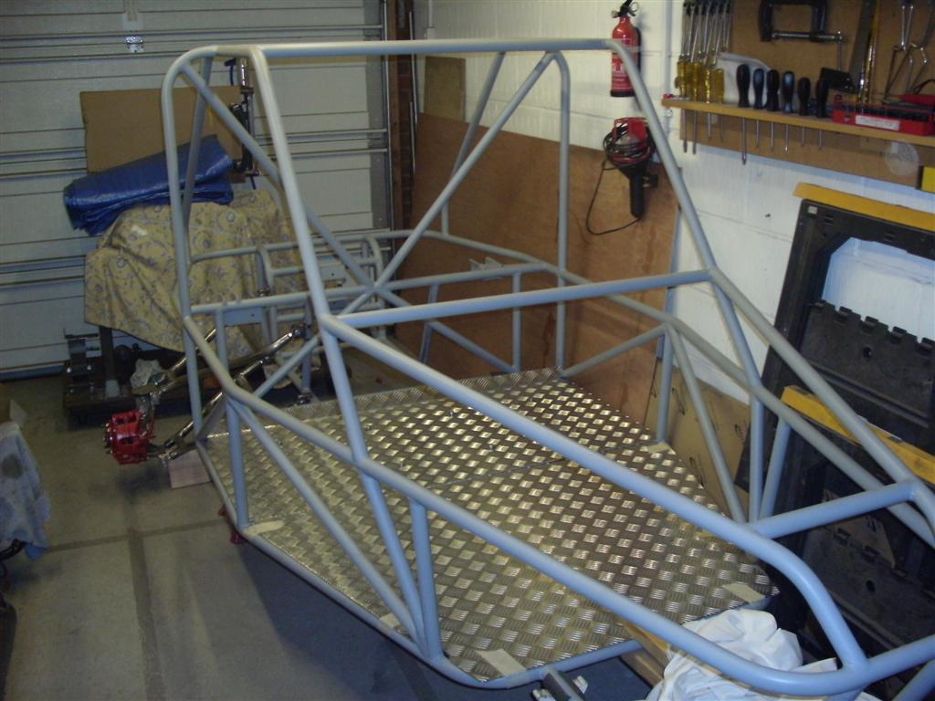
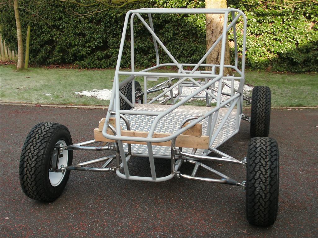
Chassis midsection and upper roll cage:-
build_diary71_web.jpg


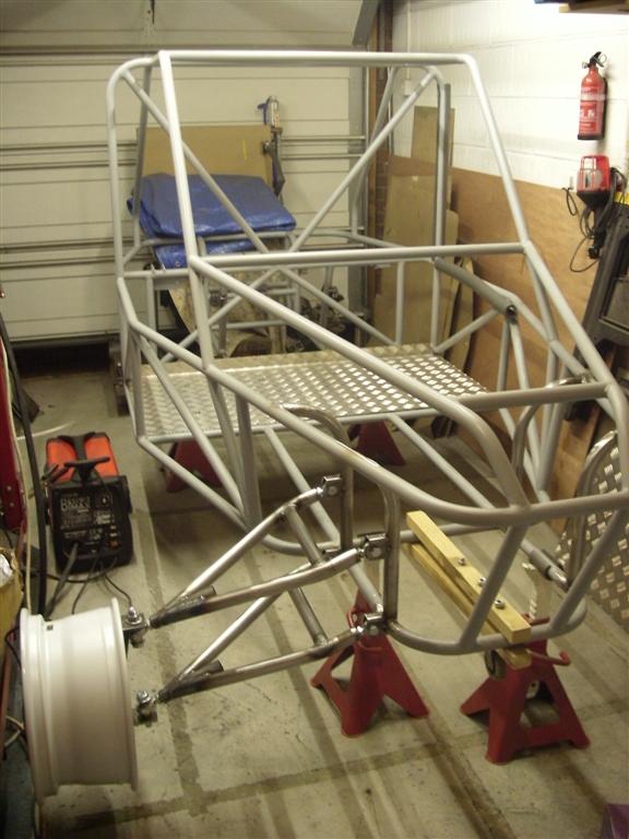
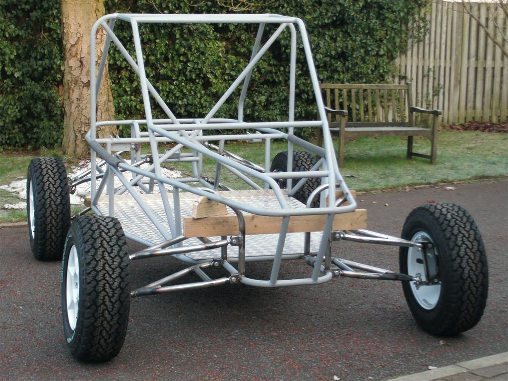
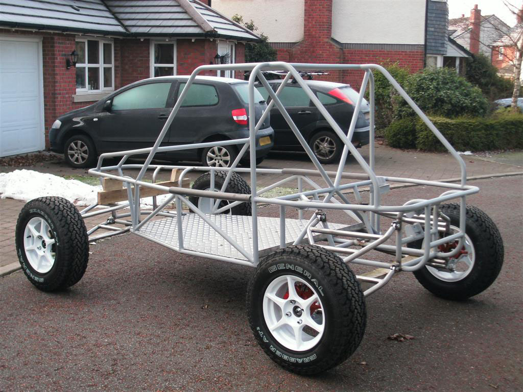
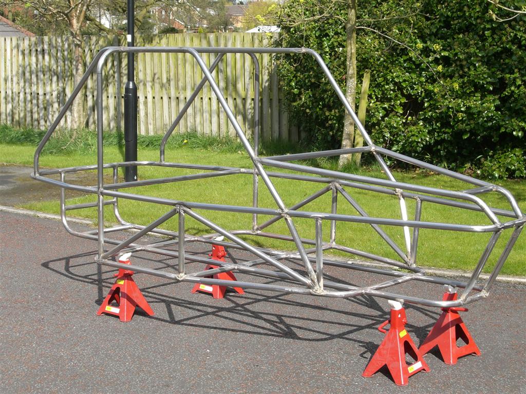
Chassis Upper section in place - starting to look right :-
build_diary94_web.jpg


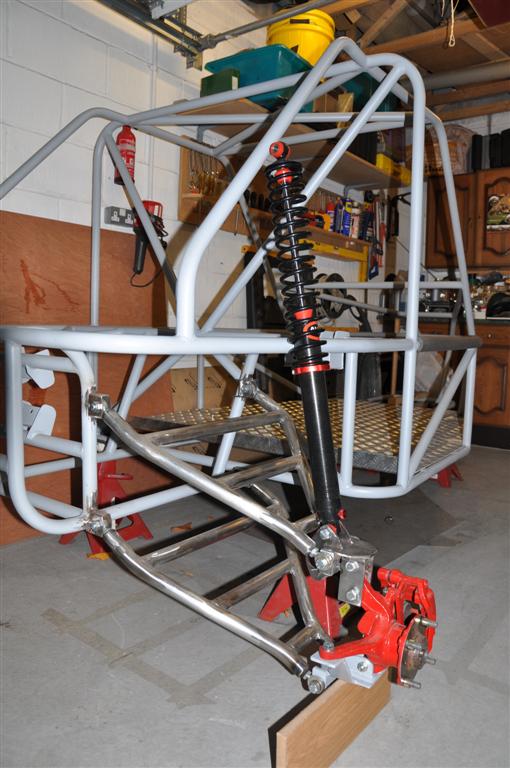
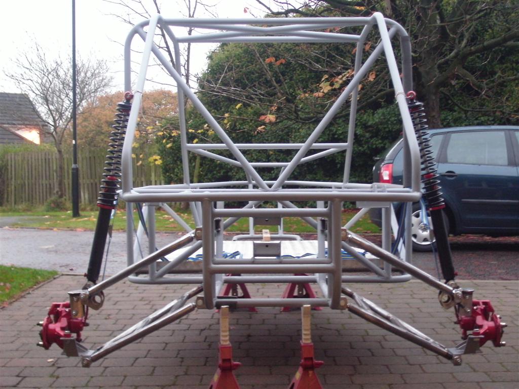
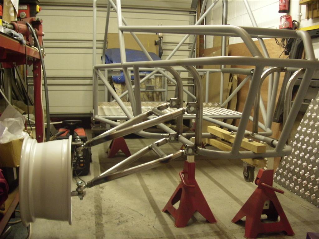
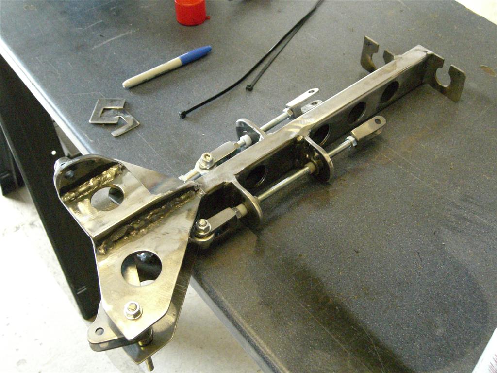
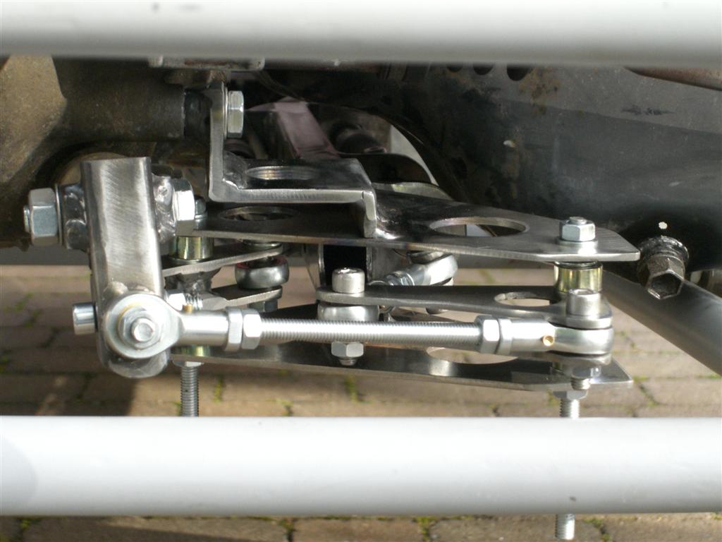
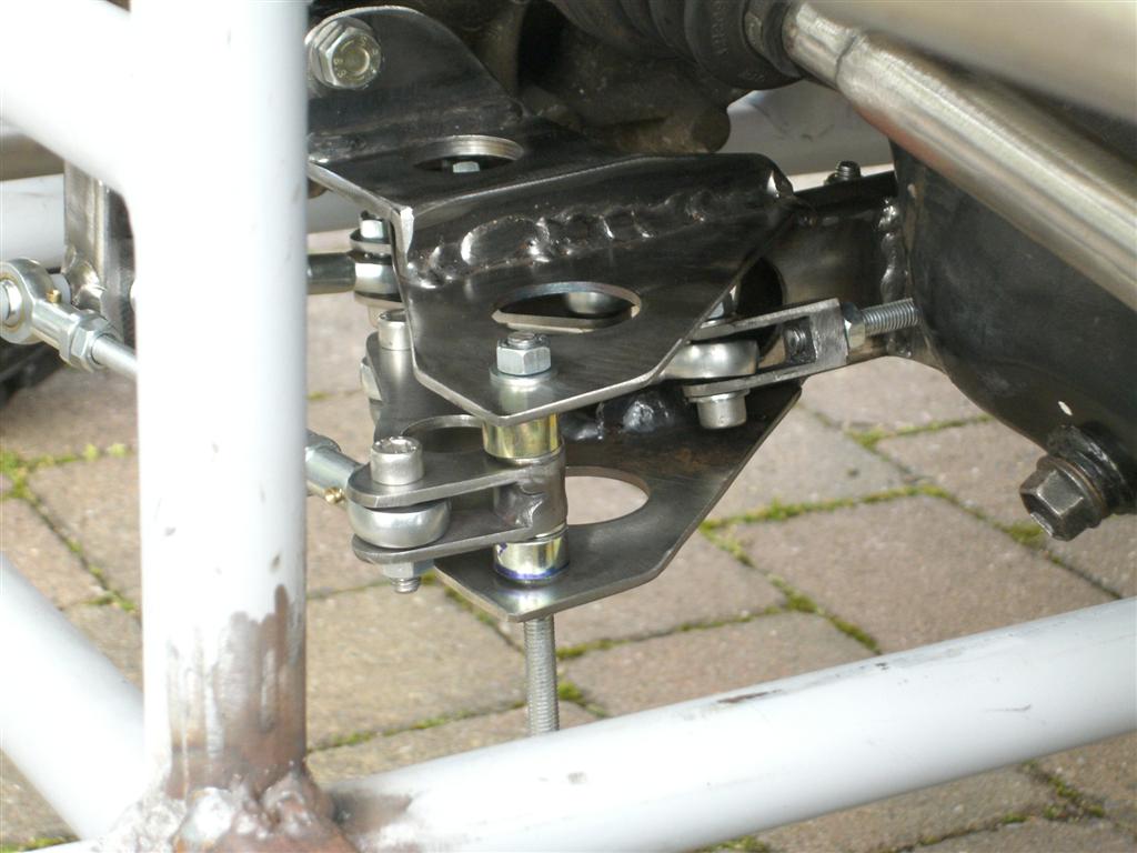
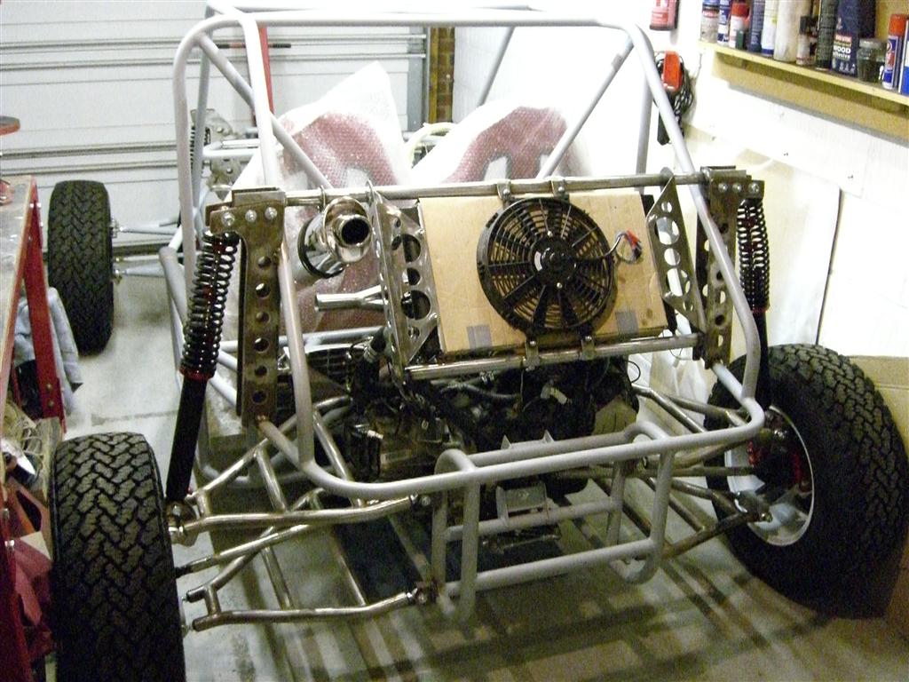
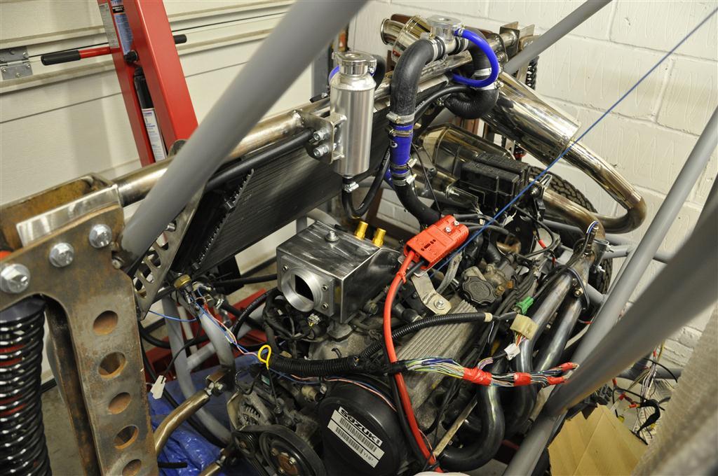
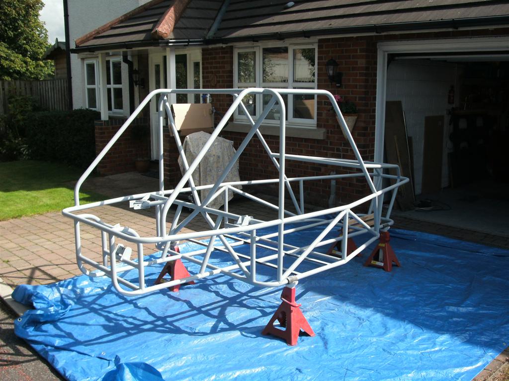
chassis with diagonals and engine mounts in place (and a bit of undercoat):-
build_diary179_web.jpg
 

ChaosMS

Active member
Here are a few pics of the suspension arms ive built - and the jig!

At it with the pipe bender again these 8 bits are the sides of the arms :-
build_diary181_web.jpg


The jig to ensure all the arms are the same and repeatable :-
build_diary183_web.jpg


finished arm with a single rose joint in:-
build_diary185_web.jpg


Both rear arms for one side mounted to the hub:-
build_diary187_web.jpg


arms and hub hung in place at the back of the chassis:-
build_diary190_web.jpg


First arm mounted correctly :-
build_diary192_web.jpg
 

ChaosMS

Active member
Final two rear suspension wishbones / A arms they need final trimming to length (note black lines on tube ends:
build_diary194_web.jpg


A couple of shots of the rear suspension in place:
build_diary197_web.jpg


and another:
build_diary198_web.jpg


And finaly a shot of the chassis with rear arms in place and new alloy floor:
build_diary207_web.jpg
 

ChaosMS

Active member
First shots of all the rear suspension mounted up - re done the lower shock mount so that it would clear the new rims I have for the project and finally dropped it onto the floor with two steel wheels (from the donor car) - which turned out to be a waste of time so I took em of again!

Anyway a few shots for you all :-

View of rear suspension showing shock location and new hub top mount (lower mount finished and now in primer-
build_diary213_web.jpg


View from rear showing all suspension and shocks (shock upper mounting hoops not done yet)
build_diary219_web.jpg


Side view with one of the new rims bolted on
build_diary221_web.jpg


Rear view with rim
build_diary223_web.jpg
 

ChaosMS

Active member
the 4 front arms built (but not finished in these shots)
build_diary235_web.jpg


And the front verticals in place ready for the suspension:
build_diary239_web.jpg


Here is a shot of the front hub adaptor I have built for the suzuki swift front hub to convert it to double a arm suspension geometry - My aim is to keep the specialised parts to an absolute minimum hence the adaptors! anyway this is what it looks like (note a rather rusty looking front hub assembly still to be cleaned and painted)
build_diary241_web.jpg

the lower rose joint plate needs a strength webbing adding to the bottom yet but were almost there.

Front Suspension mounted
build_diary242_web.jpg


And another shot of the front suspension -
build_diary243_web.jpg
 

ChaosMS

Active member
Shot of the back end with tyres fitted (General Grabber AT2 225/70/15), as its easier to roll it out as you can see its a tight fit in the garage now
build_diary247_web.jpg


Well I wanted to get the buggy to a rolling chassis stage before the end of the year - and I made it!! - with only a few hours to spare (Finished new years eve 18:00 - in the dark!!) didnt get much chance to photo anything at the time apart from the tight fit in the garage!!

See what I mean....
build_diary248_web.jpg


The next morning managed to take a few more shots herer's a few:-
build_diary250_web.jpg


build_diary254_web.jpg


build_diary256_web.jpg


build_diary258_web.jpg


build_diary259_web.jpg
 

ChaosMS

Active member
Engine back in and temp driveshafts made, sorted the steering rack mounting out

It was a nice sunny day so thought I would take a few progress shots,
build_diary280_web.jpg


build_diary283_web.jpg


build_diary284_web.jpg


build_diary287_web.jpg


And then I put her back in the garage (taken the following day after I put the proper temp driveshafts in!! (the ones in the pics above were only to get the correct length!!
build_diary297_web.jpg
 

ChaosMS

Active member
And here is the video of the walkaround
[youtube]http://www.youtube.com/watch?v=LW15_5NMyDE[/youtube]

And yes I know its called construction video no. 2 and I say its the third video... but the first vid i did on youtube was of the engine running on the stand I built for it - search for videos from TheBuggyBuilder and youll find it - thats if your really bored with nothing better to do that is!!
 

ChaosMS

Active member
Got rid of the wood at the rear - will need to change the springs on the shocks once its all finished and I have the "all up" weight.

Rear suspension mounts prior to fitting to the chassis:-
build_diary302_web.jpg


And a few once fitted (and a second one built and fitted) also shows new seat mounts and steering column mount (first of two)
build_diary323_web.jpg


build_diary325_web.jpg


build_diary326_web.jpg


build_diary329_web.jpg
 

ChaosMS

Active member
front suspension fitted
build_diary346_web.jpg


Alloy section used to house handbrake and gear shift assembly, cables atttached but layed onto to measure up!
build_diary354_web.jpg


Cut outs done for mounting cables through
build_diary365_web.jpg


Working version of the selector mechanism bare
build_diary371_web.jpg


Mechanism with push rods and cranks fitted (extended threaded rod to be swapped out)
build_diary372_web.jpg


Fitted in position at the back of the buggy! (Again the extended threaded rod is to be swapped out with correct length bolts)
build_diary379_web.jpg


build_diary377_web.jpg


A lot of work went into getting this correct, it was surprising just how much work was needed just to find out how big the cross gate crank needed to be! Anyway it works like a dream now, just enough movement across the gate and a good notchy click as it goes into each gear, overall I'm very happy  :D
 

ChaosMS

Active member
Pedal assembly designed and started cutting out the pedals, so here are a few progress shots:

Blanks rough cut-
build_diary382_web.jpg


Blanks drilled and cleaned up:
build_diary388_web.jpg


And finally welded together;
build_diary392_web.jpg


Finished Pedals
build_diary393_web.jpg


And the mounting for the pedals
build_diary407_web.jpg

build_diary408_web.jpg


This is what it looks like now with spring return bar and pedal stop in place-
build_diary414_web.jpg


And finally hung in the buggy - its a snug fit :D
build_diary421_web.jpg
 

ChaosMS

Active member
Exhaust Manifold!!

build_diary424_web.jpg

Standard manifold on the right ;) just using tape to hold the primarys together for the moment

And here is one with the manifold in place;
build_diary427_web.jpg


Finished (almost) off the manifold and took a couple of shots
build_diary428_web.jpg


build_diary430_web.jpg


build_diary444_web.jpg

Radiator mount finished and fitted (Rad core is covered in cardboard in this shot

build_diary442_web.jpg

close shot showing back box in place and side view of the rad mount.
 

ChaosMS

Active member
Well it was sunny this weekend so I thought I would push the buggy back out of the garage and take a few shots, not as much done recently as I would have liked but made the roof mounted spare wheel carrier, the lap bar, fitted (and modded) the column switch gear, and finished the exhaust off!

I plan to get the engine running this coming weekend and I will post another video of it running ! (All being well)

Anyway here is how she looks at the moment-
build_diary460_web.jpg
 

ChaosMS

Active member
Been busy making the new airbox and fitting the Induction / filter system so time for a quick update -here are a few pics!

Sheet metal parts cut out and drilled ready for assembly;
build_diary461_web.jpg


Completed Airbox seam welded finished ready for paint;
build_diary462_web.jpg


Fitted to Injection system;
build_diary464_web.jpg


Induction pipework with silicon joiners and airfilter fitted;
build_diary465_web.jpg


Induction system joiner shown fitted (but not clamped) to airbox;
build_diary466_web.jpg


Back to the wiring loom tomorrow!
 

ChaosMS

Active member
Been busy this weekend working on the dashboard here are a few pics

Dashboard panels cut out ready for assembly
build_diary467_web.jpg

Panels tack welded together
build_diary473_web.jpg

Fully welded and finished (just about)
build_diary478_web.jpg

And with the dash dropped into position
build_diary486_web.jpg


Still have the bolt down lid to finish off but I'm happy with the dash so far!
 

ChaosMS

Active member
It was like Christmas at my house today! - the fuel tank that was made to my drawings by ProAlloy (And they did a fantastic job I reckon) and the gauges that were built for my engine by ETB instruments arrived!!! here are a couple of pics;
build_diary488_web.jpg

Fuel tank showing breather/feed/return ports filler and Sender port (under the tape in the middle) and the turned pot at the bottom is the fuel sump!
Note top right - the earth tab on the tank that is now an IVA requirement!
build_diary490_web.jpg

And the matching set of gauges (Rev counter built specifically to switch between 3 and 4 cylinders.

What do you think?
 

ChaosMS

Active member
Not got as much done this weekend as I wanted but did get the ECU mounts within the dashboard made and fitted (its on rubber anti vibration mounts now) and the dashboard mounting tabs are now welded in place, I dropped the gauges into the dash for a quick pic! so here you go -
build_diary493_web.jpg
 

ChaosMS

Active member
Well got a bit more done this weekend decided to fit the front lamps so fabbed up these mental lamp brackets! due to the narrow nose and long suspension arms the lamp brackets had to lower the main lamp (To comply with the 1200mm max height from floor IVA rule) and push it out towards the wheel quite a long way (To comply with the 400mm to outside edge of vehicle IVA rule) Anyway here are a few pics

Plate cut and drilled ready for welding -
build_diary494_web.jpg


Tacked together -
build_diary498_web.jpg


One finished and on (clamped in position) -
build_diary497_web.jpg


Both finished and clamped on -
build_diary500_web.jpg


I think they look a little mental, but hey so does the rest eh!!

Lamps are a 7 inch rubber cased unit and the indicators are rubber stalked bike type!
 

ChaosMS

Active member
Well a quick update now I'm back from my hols and working on the Buggy again! - I have been working on the engine loom and extending the ECU harness so that the ECU will fit into the dashboard correctly anyway a couple of shots of the engine harness removed from the engine and stripped of its factory black sticky mess!

Shot one harness stripped of its black loom bind ready for cleaning and modification;
build_diary502_web.jpg


And after cleaning new blue cable guard and a good coating of blue silicone tape (the rubber stuff that sticks to itself not the wire or plastic!
build_diary503_web.jpg


More soon!  ;D
 
Top